For some time I've been working at stuffing a waveguide and woofer tightly into a corner so as to not have to worry about boundary reflection nulls, to take advantage of the corner gain, and to achieve a wide sweet spot. Midway through this research and design process I discovered Synergy horns and started moving in that direction. Now I'm on 2nd generation cabinets and third generation horn hoping these will finish well enough to be considered done.
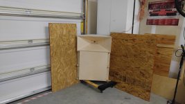
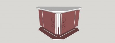
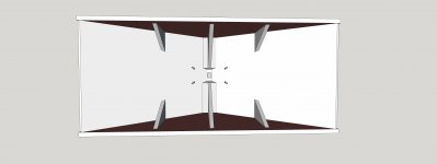
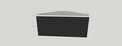
The attachment shows the concept and the look I'm trying to achieve. Its implemented as a sandwich of a Synergy horn cabinet between two triangular bass bins that each contain a 15" slot loaded woofer and horn flares that direct the bass out vertical slots on the sides. These are hidden behind black perforated metal grills. The Synergy is 90H x 45V and is 12" tall at the mouth. The stack is 66" tall and 29" wide. The vertical horn wall will end up 3.5" from the room wall.
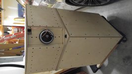
The attached photo shows my status. I've got two bass bins and one horn built and sufficient measurements done to know they will work. My plan is to finish these (i.e. apply veneer) , get help moving them upstairs into my media room, and then fix up my CAD files for another trip to my local CNC shop for the next set.
I will post more details tomorrow.
The attachment shows the concept and the look I'm trying to achieve. Its implemented as a sandwich of a Synergy horn cabinet between two triangular bass bins that each contain a 15" slot loaded woofer and horn flares that direct the bass out vertical slots on the sides. These are hidden behind black perforated metal grills. The Synergy is 90H x 45V and is 12" tall at the mouth. The stack is 66" tall and 29" wide. The vertical horn wall will end up 3.5" from the room wall.
The attached photo shows my status. I've got two bass bins and one horn built and sufficient measurements done to know they will work. My plan is to finish these (i.e. apply veneer) , get help moving them upstairs into my media room, and then fix up my CAD files for another trip to my local CNC shop for the next set.
I will post more details tomorrow.
Attachments

Looks like a neat concept. I think you'll still get boundary nulls from ceiling and floor, though. The lower vertical pattern control frequency for the rectangular horn will be much higher than for horizontal propagation, so there will be reflections off the floor (causing a null at I'm guessing around 150-230Hz) and one from the ceiling also. I have that issue on my Synergy clones, too. Allison effect is a bitch.
It wouldn't be as nice cosmetically, but have you considered making a square rather than rectangular horn so the vertical is controlled better? The vertical angle would be wider but would extend down to more useful frequencies. To make a narrower angle to a given frequency, the horn has to be (against intuition) larger in dimension, so the narrower angle causing a smaller dimension hurts quickly.
It wouldn't be as nice cosmetically, but have you considered making a square rather than rectangular horn so the vertical is controlled better? The vertical angle would be wider but would extend down to more useful frequencies. To make a narrower angle to a given frequency, the horn has to be (against intuition) larger in dimension, so the narrower angle causing a smaller dimension hurts quickly.
Last edited:
Nice Carolina Hurricanes poster. I lived in NC when the Canes still played in Winston Salem/Greensboro.
Looks good. Maybe you can improve the horn termination on the mouth side. That would prevent the sound from reflecting back into the horn. It would also prevent beaming around the lower frequencies, where the horn loses pattern control. A second flare with a larger angle or a huge rollover would work.
Very nice! Sort of like a MTM with proper C to C distances tucked away in a corner...
As the bass bins are closed above and below in the mid sections, couldn't one extend the synergy horn shape in the middle? I believe I once saw a proposal from you to do something like that. The front panels of the bass bins would no longer be flat but bulging in the middle (half round) to accommodate the larger horn shape, more of an extending lip actually.
Looks like a neat concept. I think you'll still get boundary nulls from ceiling and floor, though. The lower vertical pattern control frequency for the rectangular horn will be much higher than for horizontal propagation, so there will be reflections off the floor (causing a null at I'm guessing around 150-230Hz) and one from the ceiling also. I have that issue on my Synergy clones, too. Allison effect is a bitch.
It wouldn't be as nice cosmetically, but have you considered making a square rather than rectangular horn so the vertical is controlled better? The vertical angle would be wider but would extend down to more useful frequencies. To make a narrower angle to a given frequency, the horn has to be (against intuition) larger in dimension, so the narrower angle causing a smaller dimension hurts quickly.
As the bass bins are closed above and below in the mid sections, couldn't one extend the synergy horn shape in the middle? I believe I once saw a proposal from you to do something like that. The front panels of the bass bins would no longer be flat but bulging in the middle (half round) to accommodate the larger horn shape, more of an extending lip actually.
To OP: What you are describing and showing is very similar to the split Jubilee corner horn bass bin design by Tom B. He is using a K-402 from 400 Hz on up, not needing a multiple entry horn for that band. Tom puts his K-402 between the two bass bins. Here is a link to the half-height bass bins: https://community.klipsch.com/index...alf-bins-great-for-a-center-channel-or-rears/
They work very well. Floor and ceiling bounce (...Roy Allison wasn't the first to describe the effect...neither was Klipsch...) isn't an issue with these like you see with direct radiating bass bins.
Yours is a nice implementation - congrats. That's what I'd do if using folded bass horns since it reduces the acoustic vertical offset to a minimum for the bass bins vs. the multiple-entry horn. The improvement in imaging and midbass performance is significant over a typical Khorn or Jubilee setup.
Chris
Last edited:
Thanks to all. I'm gratified by the responses.
Bwaslo: you are right re' ceiling and floor reflections. That is why I added the 2nd woofer which should control vertical from a 200 down more than an octave. I see a big floor bounce null in my hard floored garage but hardly noticeable upstairs in my carpeted media room. Throw rugs are my friend. I hope I can do without ceiling treatment.
I've drawn up a secondary flare to slide onto the sides of the horn (like the SynTrip); I doubt my wife will like how it looks but an engineer certainly would. I would blend it into the walls on the sides and use large roundovers top and bottom. Since I went sealed instead of ported for the woofers, I don't need the extra woofer volume that would allow. First I want to see how well it does without a secondary flare. We can all discuss that more later; its an interesting topic.
HIPCHECK: I was wondering what a hockey player was doing in Arkansas. I just retired from the Hillsborough Adult leagues two years ago due to a worn out back and age.
Cask: Very impressed with the Jubilee and your Synergization of it. Thanks for the link.
Jack
about the bass bins
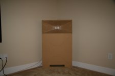
When I started aiming for the corners I researched classical corner horns, focusing on Khorn and Jubilee. They had impressive sensitivity but not as much extension as I wanted. Following Wayne Parham, I built a ported prototype - same approach as I ended up with but taller and deeper; about twice the volume - using an AE TD12X I picked up in the infamous group buy a several years ago. This is the first attached photo.
The design tune was 35 Hz but I ignored vent proximity effects and ended up with a 29 Hz tune. When I hauled it upstairs I found a huge room mode peak right at 40 Hz. The quick fix was to close off the vent. It was still -3 db at 25 Hz. It was then I knew I should go sealed.
Going sealed though called for more extension so I upgraded to TD15Hs. This time they only took about a month to arrive. I shrunk the box height to 26" for a volume of 65L and a Qtc stuffed of .65 or so.
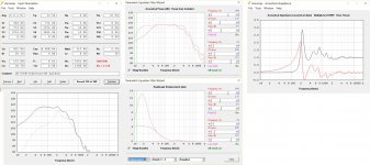
These boxes have 3" deep slot with flares to direct the sound out to the sides. I modeled them in HornResp and simulated in 4pi space then included a room gain profile exported from Jeff Bagby's Diffraction and Boundary Simulator. This models a side slot as a radiator and includes the reflection from the opposite side wall, which limits the high end extension (although not as much as does the split horn path when you get off axis). This model is optimistic on the high side because it includes a V shaped reflector in the baffle hole (where a phase plug might go) that reduced the Vtc. I dropped that deflector in the interest of simplicity when measurements showed it bought me only 50 Hz, which I didn't need. You can see the acoustic impedance taking off from the horn gain at 200 Hz, delaying the response fall off due to the bandpass chamber effect of the slot.
In the sim I'm modelling two drivers in twice the volume, ignoring their physical separation. Equalized flat to 20 Hz, I get 123 db SPL at Xmax. I don't listen nearly that loud so I'm confident I have a low distortion solution.
I'll post some build photos and measurement results shortly.
Jack
When I started aiming for the corners I researched classical corner horns, focusing on Khorn and Jubilee. They had impressive sensitivity but not as much extension as I wanted. Following Wayne Parham, I built a ported prototype - same approach as I ended up with but taller and deeper; about twice the volume - using an AE TD12X I picked up in the infamous group buy a several years ago. This is the first attached photo.
The design tune was 35 Hz but I ignored vent proximity effects and ended up with a 29 Hz tune. When I hauled it upstairs I found a huge room mode peak right at 40 Hz. The quick fix was to close off the vent. It was still -3 db at 25 Hz. It was then I knew I should go sealed.
Going sealed though called for more extension so I upgraded to TD15Hs. This time they only took about a month to arrive. I shrunk the box height to 26" for a volume of 65L and a Qtc stuffed of .65 or so.
These boxes have 3" deep slot with flares to direct the sound out to the sides. I modeled them in HornResp and simulated in 4pi space then included a room gain profile exported from Jeff Bagby's Diffraction and Boundary Simulator. This models a side slot as a radiator and includes the reflection from the opposite side wall, which limits the high end extension (although not as much as does the split horn path when you get off axis). This model is optimistic on the high side because it includes a V shaped reflector in the baffle hole (where a phase plug might go) that reduced the Vtc. I dropped that deflector in the interest of simplicity when measurements showed it bought me only 50 Hz, which I didn't need. You can see the acoustic impedance taking off from the horn gain at 200 Hz, delaying the response fall off due to the bandpass chamber effect of the slot.
In the sim I'm modelling two drivers in twice the volume, ignoring their physical separation. Equalized flat to 20 Hz, I get 123 db SPL at Xmax. I don't listen nearly that loud so I'm confident I have a low distortion solution.
I'll post some build photos and measurement results shortly.
Jack
Attachments
Yes. I will get to that but not right away. I need to get the speakers installed in room to do that and they aren't finished yet. Meanwhile the pictures I wanted to post have been stuck in the outbox of my phone....
Internal structure of the bass cabs
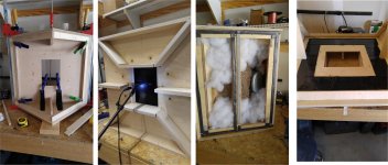
First picture (of the top of the bass cabinet being glued on) shows the internal structure. I had to go with removable sides to have access to the driver; thus the framework around the outside of the top and bottom plates.
Not shown are the removable vertical center brace in the middle of each side allowing the driver to be removed if necessary. These braces are double thick and relieved .25" in back at the midpoint to clear the driver frame during insertion and removal.
The 7" x 10" hole through the baffle results in a compression ratio of 1.9:1.
The second picture shows the flares in front of the baffle, all fitting nicely into dadoes, thanks to CNC.
The third picture shows the pillow stuffing with a piece of burlap used to keep the stuffing away from the cone. In this picture you can see the foam weatherstrip gaskets I used to ensure an airtight seal and also the rope caulk I added later for damping. I would have used more of this rope caulk but I was afraid it would be too sticky and I'd later be unable to remove the sides.
The fourth picture shows the 4" wide 1/8" thick sorbothane strips the driver mounting plate sits on. Additional sorbothane was added to cover the driver mounting holes. The driver in turn sits on the plate and is isolated from it by the thick rubber gasket provided by AE. The mounting screws, all of 2.25" long, are isolated from the driver and its gasket by a neoprene covered metal washer. With 2.5" long screws (available from McMaster Carr) I could have done a better job of isolating the screws but what I did seems to have worked. Playing 30 Hz sine waves I feel lots of vibration in the driver mounting plate but none at all in the baffle.
Jack
Attachments
measured bass response in garage
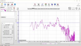
These measurements were done in the far from ideal garage corner pictured in my first post.
The raw response isn't very pretty. With frequency dependent windowing (thanks, Wesayso) it cleans up nicely. The plot with 2 waveforms is the same data contrasting 4 cycle and 8 cycle FDW traces.
With a couple of PEQs and not very much low end boost it will do nicely from 20 to above 200 Hz. I'm not sure which window to EQ with but I hope for cleaner results in room. My garage is far from ideal and these results give hope to those who need to create a false corner, as I did in the garage, to use this concept.
The false corner, doesn't have to reflect sound at the very low end of the curve; this can be done by a more distant real corner with little loss, up to some point depending on that distance.
Jack
Attachments
Horizontal polars for the bass
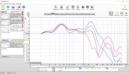
Look now at the measured polars, 4 cycle FDW, 0, 22, 33 & 45 degrees off axis. These angles are little more than eyeballed but sufficient to their purpose.
I expected a cancellation null at 200 Hz based on the geometry. In the 45 degree curve (red) you can see the response diving towards the null already at 157 Hz but the null itself is out at 238 Hz. I narrowed the front panel to just 24" to save on veneer costs, but I think this also widened the bandwidth a little bit.
At the end of the couch in my room, I'll be 22 degrees off axis from the near speaker and 7.3 degrees off axis from the far speaker. The center of the couch is 19 degrees off axis from both. (that being the case, I wonder why I didn't take data at these angles).
At my nominal planned crossover to the synergy mids of 200 Hz, I should be within 2 db across the width of the couch, due to this one effect at any rate.
Jack
Attachments
The Synergy Horns
The horn dimensions came right from BWaslo's spreadsheet. I got the mouth height and width and the horn depth from the spreadsheet for an 90x45 horn with no secondary flare. I then drew a box of those dimensions in Sketchup, drew the .707" square centered on the back and then connected up vertices. That was my horn outline. I then pulled each piece to the appropriate thickness, 12mm, made the bevels at the intersections and ended with each piece a separate component.
Construction wise, I started with identical top and bottom pieces that matched the footprint of my bass bins, except for the point of the triangle being cut off. The vertical flares insert into dadoes in the top and bottom pieces that hold them in precise alignment. These flares are machined with additional dadoes for the mid chambers, mid port holes, mid driver surround relief, and coarse "frustrumizatiion" around the mid ports. BTW, I had to fill some of this in to raise the BW past 1 Khz. Now it goes higher than it needs to so I should dig some of that filling out. The principle involved is that the shorter the mid port is, the less area it needs for the same flow velocity and of course, smaller holes means less disruption of the HF pattern.
In the second picture, you can see the structure on the other side of the vertical flares. Tight into the corners are what I call corner plugs. These fill in the gap between the two vertical flares and provide something for the screws that hold the CD mounting plate (not shown) in place to grab. All this is necessary to get access to the CD mounting screws. There are three braces for each horizontal flare. These just sit on the flares and the lips of the corner plugs for gluing.
The third picture shows a mid chamber. The sides of the mid chamber brace the vertical flares even better than the horizontal flares are braced; it feels rock solid in a knuckle rap test. The dimensions of the chamber are such that any standing waves would be out of band, except for the long dimension. The reflection from the (removable) top was a problem in my 8FE200 prototype but this version of the chamber is only 2.375" deep. The long dimension can have an inband mode but its long enough that when fully stuffed the mode is suppressed.
The beauty of the 4FE35 mid that I'm using is that they are high QTS so that the Q never gets too low no matter how big the box volume. This curiously shaped chamber lowers the resonant peak to 131 Hz (per HornResp) and associated group delay, well below my high pass crossover frequency.
Cutting horn flare angles is a challenge even for CNC. I ended up cutting the outlines on the CNC but the bevels that I didn't have V-bits for on my table saw to save machine time. It was easier than I had feared and therefore I probably won't need the perforated grill over the face of the horn that I initially conceived.
Finally a photo of the back of the stack with the now 6yr old 535 from my sig showing at the side.
Jack
Attachments


Measurement of the BMS4550 CD on the horn
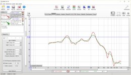
I'm getting closer to being able to do a crossover....
Here is a measurement of my CD again in the garage corner. This is gated but not smoothed; you can see the gates in the picture. I was surprised how clean and smooth it was given what some of my previous efforts looked like but I suppose part of that is the FDW.
Jack
Attachments

Looking for an explanation of the mid response
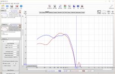
The picture shows my four 4FE35 mids; the blue curve is taken right at the horn mouth while the red curve is taken at 1m from the throat. This apparently is just enough for the room to interfere. No matter how narrow I set the gate or the FDW, I can't get that roll off below 400 Hz to go away. I expect some peaking due to horn gain starting at about 400 Hz but simulation shows the curve flat down to 100 hz.
One couldn't ask for a nicer low end response than the blue curve but what happens to the low end response in the red curve?
My first hypothesis was that it was a floor bounce null but adding absorption on the floor didn't fix. My current theory is that I'm getting side reflection nulls. At 1M from the apex of a corner the sides are about the same distance as the floor. To escape their influence I need to get 2-3 meters away!
I've already seen that I can't take H-polars at HF with the mic near the wall without jury rigging a first reflection absortion pad.
Comments?
Thanks,
Jack
Attachments
Reread Allison's paper and ran Jeff Bagby's Diffraction and Boundary Simulator.
Its definitely a boundary effect and now I recall that with my first gen prototype I used 2" fiberglass panels on the side walls and they made the mid roll off go away. Shouldn't have forgotten that. The reason I used them was to shield my TV from the horn. Didn't think I needed them regardless. Well long term plans always called for absorption on the front wall for room modes. Looks like a panel on each side wall might be in order...
Its definitely a boundary effect and now I recall that with my first gen prototype I used 2" fiberglass panels on the side walls and they made the mid roll off go away. Shouldn't have forgotten that. The reason I used them was to shield my TV from the horn. Didn't think I needed them regardless. Well long term plans always called for absorption on the front wall for room modes. Looks like a panel on each side wall might be in order...
- Home
- Loudspeakers
- Multi-Way
- My Synergy Corner Horn and Bass Bins