Hi Pacogun
Thank you for participating (have you too assembled a stack?)
You make a good point.
To answer your question straight, the 3.5A psu can not provide the current for high power operation. I have confirmed by continuous-tone testing the 2.5A demand for each miniAMP at full power.
To explain the quote from post #14:
The “attention not to overload the MiniDSP and the MiniAMPS” refers to not overdriving the input of MiniDSP and MiniAMPS which is very important, regardless of psu wattage.
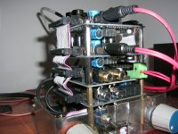
The stack is up to now in it’s most simple arrangement, that is, connected and set-up just for achieving proper functionality.
That I play my stack at a volume level that does not stress the 3.5A psu I use now, does not mean that I will leave it to that for too long.
I have made a listening session with a 10A smps psu in place of the 3.5A analog psu and the bass sensation was quite different even on medium volume settings.
The plan from the start is to power each module individually and there are a few options here.
I have e-mailed some questions to minidsp devteam for to clarify a few details in order to narrow down my decisions on how to implement this.
Now that ambient temperatures over here are declining again, I will start working with the -ever important- psu issue. 🙂
I will report on the progress.
George
Thank you for participating (have you too assembled a stack?)
You make a good point.
To answer your question straight, the 3.5A psu can not provide the current for high power operation. I have confirmed by continuous-tone testing the 2.5A demand for each miniAMP at full power.
To explain the quote from post #14:
The “attention not to overload the MiniDSP and the MiniAMPS” refers to not overdriving the input of MiniDSP and MiniAMPS which is very important, regardless of psu wattage.
The stack is up to now in it’s most simple arrangement, that is, connected and set-up just for achieving proper functionality.
That I play my stack at a volume level that does not stress the 3.5A psu I use now, does not mean that I will leave it to that for too long.
I have made a listening session with a 10A smps psu in place of the 3.5A analog psu and the bass sensation was quite different even on medium volume settings.
The plan from the start is to power each module individually and there are a few options here.
I have e-mailed some questions to minidsp devteam for to clarify a few details in order to narrow down my decisions on how to implement this.
Now that ambient temperatures over here are declining again, I will start working with the -ever important- psu issue. 🙂
I will report on the progress.
George
Last edited:
Hi Gpapag,
My apology for misunderstanding your statement.*
I am a newbie in diy audio system and*currently researching to build my own active crossover system*
using minidsp. I try to make the system as simple as*possible for a start.*
I like your configuration since it's only need 1 psu to power the whole system but then I*
stumble *upon this thread by devTeam miniDsp saying not recommend stacking 2 miniAmp over miniDsp
MiniDSP :: Topic: Re:Two MiniAMPs one MiniDIGI (1/1) .
And also, they recommend separate psu for each miniamp which for me adding the cost and complexity
MiniDSP :: Topic: Re:2.1 with 2 MiniAmp (1/2) .
However, reading from your posts, l have confidence that you don't have any problem with single psu*
as long as it has*enough ampere to power the whole stack. Do you notice any heat problems due to stacking 2*
miniAmp on the top of each other?
Pacogun
It is actually me who has to apologise as I had used the verb “overload” instead of “overdrive”
Now, my experience with miniDSP boards tells me that in practice it is easy to manage an active system.
When I started reading the data sheets I was lost but things went OK further on.
Heat build-up is not really an issue with the two miniAMPS in my stack.
I have monitored the temperature with a tiny probe and the base of the cooling fins barely reach 60 d. Celsius on any of the two amplifier boards with an ambient temp around 30 d.C. The base reached 68 d. C. (the fins were bellow 60d.) with 38 d local ambient. Besides, the stack can be positioned so that the boards are oriented vertically for better heat convection.
Regarding psu, I would suggest to start with a single psu.
Don’t complicate things looking for the theoretically optimum right from the start.
If the psu is 100-150W you can live with it, later on you can add some capacitance and filtering at the DC-In of each board.
When you will start, you will see yourself that what will attract your attention (and drain your time 😀 ) is not the hardware which is adequate for the task and well made but the numerous capabilities/huge flexibility that the DSP software provides for setting-up and adjusting your loudspeakers. 🙂
George
Last edited:
Gpapag, kudos on some quality work and reporting. I am just starting with 2 minidsp/miniamp stacks one for each 2-way speaker in simple stereo. I am having jumper issues here as I can get both 1&2 showing output on the RMS meters, but only one channel delivering signal to the speakers. I tried the config you show, but no joy.
I notice that according to the miniamp documentation you are running your speakers out of phase. They show the outputs in BTL as + -, and - + if facing the output terminals.
I notice that according to the miniamp documentation you are running your speakers out of phase. They show the outputs in BTL as + -, and - + if facing the output terminals.
Hi Jack
Thank you and welcome to the club
Please be a bit more descriptive on your configuration.
You have two stacks, each stack comprised of what boards?
What audio plug-in are you using?
From what you write, I suspect that the miniDSP works OK but the problem is with the miniAMP
Keep in mind that the miniAMP jumpers shown on post #3 are for using the 2 way + Sub (2.1) crossover plug-in.
Please look the drawings again. I know that it is very easy to do a mistake with all these small jumpers.
The speakers wiring is OK (in phase). I attach the relevant drawing from the miniAMP user manual.
I have noticed that a mistake on speaker wiring connection or a mistake on these output jumpers, may increase the current draw on the board (in addition to no signal output)
George
Attachments

Hi George, I'm Jack. Sorry my mistake about phasing.
I have 2 stacks , each of minidsp 2-4 and minicamp. I am running advanced 2.1 plug in. Output jumpers are ok. I don't want a sub right now, just simple cross for 2-way speakers.
I am assuming that I can have the same setup right across for both left and right stacks. That I have output on rms meters on output for 1 and 3 is confusing. The output never gets to the speaker terminals. Crossovers are set with ch 1 and 3, as that's where the output shows up. There is no output on 3 or 4 according to the meters. I notice that in one place, the documentation shows pin 1 of the routing heaser open and closed somewhere else. I left it open. pin2-4 closed, pin 5 closed, pins 6-12 open. This is for both stacks. the config header is: gain 0 &1 closed, conf conf 2 closed, conf 1 open, reset open.
Jack
I will try to help you although I deviate from the topic of this thread.
The problem you describe now is different from what you described in your previous post.
I can understand what is going on but before I give you a suggestion, answer me this question:
Whatever you connect to the miniDSP input as music source is only analog and will remain only analog?
George
Thanks George. I apologize for dragging you off topic. I know it's just a routing problem, as I see the low freq. output in the ch3 rms meter. Just can't figure out why it's not on ch2, and not driving the speaker. As source I am using the headphone out from my pc, so yes analog out for now. As budget permits, I may add a pair of minidigi, as my MB has SPDIF out available.
Jack
Let’s start with the miniDSP boards of each stack first and clear the possible issues there.
Remove the ribbon wires and any DC power from the miniAMP boards.
Make sure that the M/S jumper on the miniDSP boards is in the Master position.
Connect your analog signal source to IN1,IN2 of your first miniDSP board. Left analog channel to IN1 and Right analog channel to IN2
On the pc, open the 2.1 plug-in program.
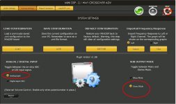
Make sure that “Analog Input” and “Stereo Mode” are selected as shown in first attachment
Connect the miniDSP board with the pc through the usb cable and synchronise.
Then monitor the Input RMS meters while your signal source plays some music.
Do you have signal on both INPUT CHANNEL 1 and INPUT CHANNEL 2 meters? You should.
If not, check the source, the interconnect cable and the Input attenuators plus the Input Mute switches of the plug-in.
Then after confirming you have signal on both input meters, look at the RMS meters of the four outputs. You should have signal on all of them.
If not, check the Output attenuators and the Output Mute switches on the plug-in as well as check for any silly setting of the cross-overs or equalizers.
When you have signal on all four output meters, stop and enjoy a beer.
Repeat the same procedure with the second miniDSP board.
Report the results here.
After you’ll finish with both miniDSP boards, have a look on the second attachment.
This will help to remember that with the 2.1 plug-in:
Output#1 and Output#3 are connected to Input#1
Output#2 and Output#4 are connected to Input#2
Think of it and we will communicate again tomorrow.
George
Let’s start with the miniDSP boards of each stack first and clear the possible issues there.
Remove the ribbon wires and any DC power from the miniAMP boards.
Make sure that the M/S jumper on the miniDSP boards is in the Master position.
Connect your analog signal source to IN1,IN2 of your first miniDSP board. Left analog channel to IN1 and Right analog channel to IN2
On the pc, open the 2.1 plug-in program.
Make sure that “Analog Input” and “Stereo Mode” are selected as shown in first attachment
Connect the miniDSP board with the pc through the usb cable and synchronise.
Then monitor the Input RMS meters while your signal source plays some music.
Do you have signal on both INPUT CHANNEL 1 and INPUT CHANNEL 2 meters? You should.
If not, check the source, the interconnect cable and the Input attenuators plus the Input Mute switches of the plug-in.
Then after confirming you have signal on both input meters, look at the RMS meters of the four outputs. You should have signal on all of them.
If not, check the Output attenuators and the Output Mute switches on the plug-in as well as check for any silly setting of the cross-overs or equalizers.
When you have signal on all four output meters, stop and enjoy a beer.
Repeat the same procedure with the second miniDSP board.
Report the results here.
After you’ll finish with both miniDSP boards, have a look on the second attachment.
This will help to remember that with the 2.1 plug-in:
Output#1 and Output#3 are connected to Input#1
Output#2 and Output#4 are connected to Input#2
Think of it and we will communicate again tomorrow.
George
Attachments

Last edited:
Ok, I have output on all. At this point maybe I have been trying to do the impossible. My intent is to run a single coax to a single input and output 2 channels which are divided in frequency by the plug-in crossover. One running the tweeter, and one the woofer. So following your guidance, I see all inputs activate all outputs, but only one output channel is connected electronically to it's speaker, even though both output meters for 1 and 3 show signal.
Hi Jack
As you understand, what you want to do can’t be done with the miniAMP in combination with the 2.1 plug-in . This is the bad news.
The good news is that it can be done with the 2 way plug-in.
I made a schematic drawing which describes in detail how to do the connections and where to place the jumpers.
The proposed solution works as is with both analog and digital sources
Cheer-up
George
Attachments

Last edited:
Info (a“must” read)
John Reekie, a member of this forum too, has presented a series of excellent articles which are of great help to anyone working on a miniDSP based system here:
miniDSP tutorials

George
John Reekie, a member of this forum too, has presented a series of excellent articles which are of great help to anyone working on a miniDSP based system here:
miniDSP tutorials
George
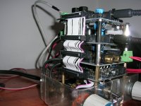
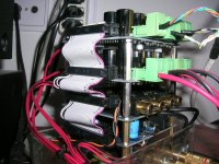
Today I made the first steps toward better DC powering arrangement on my stack.
A. I added electrolytics at the DC Input of each board (2x100uF63V on each miniAMP, 1x100uf/63v on MiniDSP, 1x100uf/63v on MiniDIGI.
B. The DC Input of each board is routed to the (still common) psu through separate wiring.
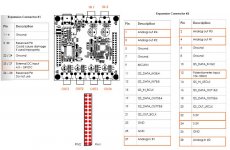
C. I cut the ribbon wires that connect pins 27,28 “External DC input
4.5 ~ 24VDC” of Expansion Connectors #1
D. I cut the ribbon wires that connect pins 22,24 “3.3V” of Expansion Connectors #2
These wires were cut for to isolate the power supply sections of the boards.
As I was on wire cutting, I also removed ribbon wires that connect pins 1,2,3,4,15,27,28 of Expansion Connector #2
Although all these were done in one go, in the end boards worked as they should with no fatalities 😀
There is still absence of turn-on/turn-off thumbs.
First listening impression is that the bass is less pronounced and more controlled.
After further listening, I think that music is more clear now (better defined) on all frequencies.
George
A. I added electrolytics at the DC Input of each board (2x100uF63V on each miniAMP, 1x100uf/63v on MiniDSP, 1x100uf/63v on MiniDIGI.
B. The DC Input of each board is routed to the (still common) psu through separate wiring.
C. I cut the ribbon wires that connect pins 27,28 “External DC input
4.5 ~ 24VDC” of Expansion Connectors #1
D. I cut the ribbon wires that connect pins 22,24 “3.3V” of Expansion Connectors #2
These wires were cut for to isolate the power supply sections of the boards.
As I was on wire cutting, I also removed ribbon wires that connect pins 1,2,3,4,15,27,28 of Expansion Connector #2
Although all these were done in one go, in the end boards worked as they should with no fatalities 😀
There is still absence of turn-on/turn-off thumbs.
First listening impression is that the bass is less pronounced and more controlled.
After further listening, I think that music is more clear now (better defined) on all frequencies.
George
Attachments
Last edited:
Hi George,
Forgive my noobie-ness.
Is this what you are trying to do with post #37 point A? Bypass Capacitor?
The Basics - Bypass Capacitors
Paul
Forgive my noobie-ness.
Is this what you are trying to do with post #37 point A? Bypass Capacitor?
The Basics - Bypass Capacitors
Paul
Paul
As long as I don’t provide measurements, whatever my answer is, it will be an assumption or a wishful thinking 😀
Anyway, the rationale is the caps to function as local power banks (ripple reduction) on miniDSP and miniDIGI and on miniAmp as noise filter caps, for to reduce ringing and spikes at the psu-amp dc wiring caused due to wiring inductance reaction to current flow di/dt.
Capacitors is an interim step which may be of no use if individual PSUs are built and placed near the boards.
George
The pictures of stack are not very clear. It can be used as an alternative power source. I guess we can use this in place of a normal inverter battery as well. Thank you for sharing this idea with us.
------------------------------------------
Ellery
snoring mouth piece
------------------------------------------
Ellery
snoring mouth piece
- Status
- Not open for further replies.