I have written that I have observed some HF radiation issues around coil L1 at the 2x4 miniDSP board
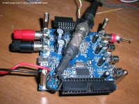
Using my spare old 2x4 MiniDSP board (v1.3), I decided to investigate the issue a bit in detail. (*)
The board takes a DC Input from 4.5 to 24V.
This DC is fed to the onboard DC-DC stepdown buck switching regulator built around LM2841Y which is switching at 1.25MHz
The converter outputs 3.3Vdc
http://www.ti.com/lit/ds/symlink/lm2841.pdf
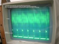
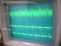
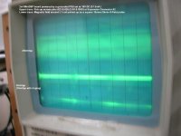
I supplied the board (stock, no added capacitance at the DC-In) through a bench stabilized variable PSU and monitored the input current, the magnetic field around L1 and the 3.3Vdc at the supply pins of the ADAU 1701, the DSP IC of the board http://www.analog.com/static/imported-files/data_sheets/ADAU1701.pdf
(The +3.3V is routed to and is identical with that of pins #22, #23 and the GND at pin #26 of Expansion Connector #2).
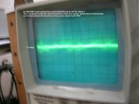
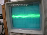
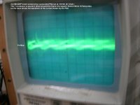
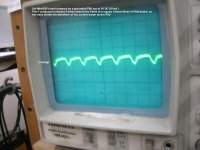
The result of the observation is that there appears pulses of 1.25MHz (and it’s higher harmonics) at the input current, the magnetic field around L1 and at the 3.3Vdc.
The effect becomes more pronounced when the DC-In voltage increases.
It is minimum at 5Vdc and goes to maximum at 24Vdc.
The harmonics really take off from 8Vdc and up.
George
(*) I have an oscilloscope that has a –3db bandwidth of 20MHz only, so the collected data (and the lousy photos) are somehow misleading at high freq harmonics both in amplitude as well as on details due to not so good triggering of the scope.
Using my spare old 2x4 MiniDSP board (v1.3), I decided to investigate the issue a bit in detail. (*)
The board takes a DC Input from 4.5 to 24V.
This DC is fed to the onboard DC-DC stepdown buck switching regulator built around LM2841Y which is switching at 1.25MHz
The converter outputs 3.3Vdc
http://www.ti.com/lit/ds/symlink/lm2841.pdf
I supplied the board (stock, no added capacitance at the DC-In) through a bench stabilized variable PSU and monitored the input current, the magnetic field around L1 and the 3.3Vdc at the supply pins of the ADAU 1701, the DSP IC of the board http://www.analog.com/static/imported-files/data_sheets/ADAU1701.pdf
(The +3.3V is routed to and is identical with that of pins #22, #23 and the GND at pin #26 of Expansion Connector #2).
The result of the observation is that there appears pulses of 1.25MHz (and it’s higher harmonics) at the input current, the magnetic field around L1 and at the 3.3Vdc.
The effect becomes more pronounced when the DC-In voltage increases.
It is minimum at 5Vdc and goes to maximum at 24Vdc.
The harmonics really take off from 8Vdc and up.
George
(*) I have an oscilloscope that has a –3db bandwidth of 20MHz only, so the collected data (and the lousy photos) are somehow misleading at high freq harmonics both in amplitude as well as on details due to not so good triggering of the scope.
Attachments
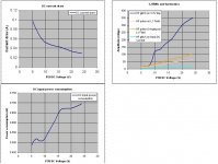


I would say that it would be better to feed the board with 5-6Vdc, no higher.
The same DC-DC switching voltage regulator is used on the newer (v1.8) MiniDSP board I have (with some peripheral component values differing), as well as on MiniDIGI and MiniAMP boards. Therefore the issue is of interest to me and I am working on it.
George
The same DC-DC switching voltage regulator is used on the newer (v1.8) MiniDSP board I have (with some peripheral component values differing), as well as on MiniDIGI and MiniAMP boards. Therefore the issue is of interest to me and I am working on it.
George
Attachments
-
 13 H-Field probe over MiniDSP board.JPG349.3 KB · Views: 192
 -
 12 V pick-up.JPG427 KB · Views: 170
 -
 11 PSU current 24V.JPG139.7 KB · Views: 145
 -
 10 PSU current 18V.JPG145.7 KB · Views: 135
 -
 9 PSU current 12V.JPG142.6 KB · Views: 132
 -
 8 PSU current 8V.JPG138.8 KB · Views: 138
 -
 7 PSU current 5V.JPG146.4 KB · Views: 153
MiniDIGI jumper settings and Input selectors connection
George
Hello George
After many hours of research I found in your article almost all the answers I needed for my project... my only difference is that instead of 2 MiniAMPs I want to route the I2S data from the MiniDSP to 2 CurrymanDACs...
Also I have the USB streamer and not the MiniSTREAMER...
Can you give me some advice on connecting the 2 CurrymanDACs to the MiniDSP?
Also it would be very nice to know what switch or correct specs of the switch you used for toggling between the 4 digital inputs on the MiniDIGI... so I can print it and try to find one near my home.
Congratulations for the project! Hope to hear from you soon...
Thank you Andre
Regarding the connection to the CurrymanDACs, I would agree with Curryman’s post without adding anything different.
MiniDSP :: Topic: USBStreamer>MiniDSP>Curryman DAC (2/3)
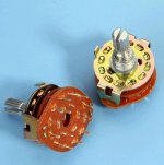
Regarding the switch, I used a simple and cheap 3 pole- 4 position rotary selector. I utilised one pole only.
It has to be a “Brake Before Make” type, which means that the moving toggle should come clear from one position to the other without shorting (electrically connecting) them while in transit.
George
Regarding the connection to the CurrymanDACs, I would agree with Curryman’s post without adding anything different.
MiniDSP :: Topic: USBStreamer>MiniDSP>Curryman DAC (2/3)
Regarding the switch, I used a simple and cheap 3 pole- 4 position rotary selector. I utilised one pole only.
It has to be a “Brake Before Make” type, which means that the moving toggle should come clear from one position to the other without shorting (electrically connecting) them while in transit.
George
Attachments
Hehe Nice to know you were also following my post on the other fórum.
Much thanks for your help, I will tomorrow search in some stores if I can get this part... Should I take care trying to find the rotary switch of higher quality for no interference on áudio signal?
Much thanks for your help, I will tomorrow search in some stores if I can get this part... Should I take care trying to find the rotary switch of higher quality for no interference on áudio signal?
I did a search for CurrymanDAC because I didn’t know it and I found the response of Curryman to your question. (This is a nice DAC).
Ref selector, I would care for a good, stable force between the toggle and the contact points.
For now, other “qualities” of the selector (contact point details like kind of metal ect) are for me not essential.
George
Ref selector, I would care for a good, stable force between the toggle and the contact points.
For now, other “qualities” of the selector (contact point details like kind of metal ect) are for me not essential.
George
Last edited:
Thank you very much for your help! I already have the rotary switch 🙂
Would it be possible to connect from USBStreamer to MiniDIGI using Toslink but not through optical connection? I mean similar to what you did with the SPDIF soldering cables below the boards on the pins of the SPDIF connectors?
What would be the disadvantages of not using the optical vs using an "electrical" toslink connection?
For the USBStreamer, I have seen they solder a cable below the board at the data pins of the TOSLINK connector.
If you connect the other end of that cable to the SPDIF-IN of the miniDIGI, I think that there will be no disadvantage (compared to an optical connection) because there are two isolation transformers there, one for each SPDIF Input.
George
If you connect the other end of that cable to the SPDIF-IN of the miniDIGI, I think that there will be no disadvantage (compared to an optical connection) because there are two isolation transformers there, one for each SPDIF Input.
George
Hmm só no problem. But you mean TOSLINK IN on the MiniDIGI (?)
Sent from my RM-885_eu_euro2_318 using Tapatalk
Sent from my RM-885_eu_euro2_318 using Tapatalk
😀 so Toslink out from USBStreamer to Spdif IN in MiniDIGI. Why like that and not Toslink IN in MiniDIGI.? Thanks for sharing your knowledge!
Sent from my RM-885_eu_euro2_318 using Tapatalk
Sent from my RM-885_eu_euro2_318 using Tapatalk
Meira, I may have misunderstood your initial question here:
So, for to make things clear, here are your three (excluding the I2S connectivity) options:
A. USBStreamer Toslink-Out to MiniDIGI Toslink-In (1 or 2) using an optical interconnect.
This is the proper interconnection with good termination and galvanic isolation between the two boards.
B. USBstreamer Toslink-Out pins underneath the PCB to MiniDIGI SPDIF-In (1 or 2) using an electrical interconnect (coaxial wire).
I have read that this is a functional interconnection method. It certainly provides galvanic isolation between the two boards.
I can not commend on the termination quality of this option, as I do not have a USBstreamer board to check.
C. USBstreamer Toslink-Out pins underneath the PCB to MiniDIGI Toslink-In (1 or 2) pins underneath the PCB using an electrical interconnect (coaxial wire). I think this is the connection you are refering to in your last post.
I would not recommend this option because it does not provide galvanic isolation between the two boards and I am afraid it will cause mismatched termination.
I don’t know if it is a functional interconnection.
You may try it and see. Pay attention to which pins you will solder the wires.
George
Would it be possible to connect from USBStreamer to MiniDIGI using Toslink but not through optical connection? I mean similar to what you did with the SPDIF soldering cables below the boards on the pins of the SPDIF connectors?
So, for to make things clear, here are your three (excluding the I2S connectivity) options:
A. USBStreamer Toslink-Out to MiniDIGI Toslink-In (1 or 2) using an optical interconnect.
This is the proper interconnection with good termination and galvanic isolation between the two boards.
B. USBstreamer Toslink-Out pins underneath the PCB to MiniDIGI SPDIF-In (1 or 2) using an electrical interconnect (coaxial wire).
I have read that this is a functional interconnection method. It certainly provides galvanic isolation between the two boards.
I can not commend on the termination quality of this option, as I do not have a USBstreamer board to check.
C. USBstreamer Toslink-Out pins underneath the PCB to MiniDIGI Toslink-In (1 or 2) pins underneath the PCB using an electrical interconnect (coaxial wire). I think this is the connection you are refering to in your last post.
I would not recommend this option because it does not provide galvanic isolation between the two boards and I am afraid it will cause mismatched termination.
I don’t know if it is a functional interconnection.
You may try it and see. Pay attention to which pins you will solder the wires.
George
Last edited:
You have just nailed it 🙂 That was exactly my idea the 3rd option and this is because once rhe boards are in the same enclosure I am searching for not having to run a cable to the outside and then to the panel mount Spdif of the MiniDIGI...
Maybe the I2S is the way to Go but from Minidsp I don't understand very clear this possibility. What do you think as for the I 2S connection between both?
Thanks for all your Help George! Precious...
Sent from my RM-885_eu_euro2_318 using Tapatalk
Maybe the I2S is the way to Go but from Minidsp I don't understand very clear this possibility. What do you think as for the I 2S connection between both?
Thanks for all your Help George! Precious...
Sent from my RM-885_eu_euro2_318 using Tapatalk
I see.
If you don’t have both of MiniDIGI’s SPDIF-In already reserved for other sources, you can opt for option ‘B’.
I2S should work fine for short wire run.
I suggest you e-mail DevTeam your specific question (don’t forget to specify if you need multi-channel or stereo -two channel-connectivity).
They answer within two-three days.
They have answered all my e-mails so far , even the strange ones.
If you get their answer, you can post it here. Some members will be benefited.
George
Last edited:
Already contacted MiniDSP, lets see what they say and I will gladly post it here.
As for the option B and my "problem" with the panel mount I can always desolder one of the SPDIF Coaxial conector of the board and solder the cable from the TOSLINK OUT in USBStreamer to the board of the MiniDIGI, and thus I don't have to run a cable to the outsider...
I am just trying to find the pins information of the USBStreamer Toslink Connector.
MiniDSP :: Topic: Re: USBStreamer to miniSHARC? (1/2)
Verify with a voltmeter the position of the +3.3V pin and Ground pin.
George
Verify with a voltmeter the position of the +3.3V pin and Ground pin.
George
OOhhh this is great help! 🙂 I tried to find it because you mentioned it before you had already seen this but I couldn't find the info...
The SPDIF coaxial conector on MINIDIGI is only 2 pins right? I should connect Ground and SPDIF signal only? why find the 3,3v?
Thanks and sorry for flooding your post! I will open a new one for my installation...
The SPDIF coaxial conector on MINIDIGI is only 2 pins right? I should connect Ground and SPDIF signal only? why find the 3,3v?
Thanks and sorry for flooding your post! I will open a new one for my installation...
Yes Meira. You will connect ground and SPDIF lines only.
The 3.3Vdc is there for to supply the optical transmitter. You will not connect anything at this pin.
I wrote you to identify the location of this pin with a voltmeter only for to make sure that you will attach the wires at the other two pins and leave this pin unconnected . Sorry if I confused you.
George
MiniAmp Power up / down behavior ?
Hello George,
many thanks for sharing your work ! I am building a similar stack - but with a 3 way configuration with a true mono separation - so I have one Minidsp stacked with one Miniamp for each stereo channel separately.
I was using the Expansion Connector #1 to use the ribbon cable to provide the power to the minidsp, but was not satisfied, caused by residual and remarkable high frequent noise/hiss with the connected speakers.
By removing EC #1 and attaching the power lines (+ 12 V using a standard 7812 Voltage Regulator) to the separate minidsp power connection, the noisy hiss is gone.
Have you ever tried, to omit the ribbons for Expansion Connector #1 ?
If that is a working configuration, will it impact the sound ?
Or is this needed for the MiniDigi / miniStreamer in your Config ?
I am using a high efficiency tweeter connected to the miniamp in SE mode and I hear a short 'chuck' from my tweeter when I switch of the stack . Can this be a 'discharge' from the coupling capacity in SE mode ?
Did you ever test SE mode on miniamp for switch on/ off thumbs ?
I am already thinking to create a simple circuit, which will pull down the PDN pin on Miniamp to ground, before the power supply capacitors will discharge. But first tests, by placing a jumper on PDN/GND also resulted in big thumbs... So I am asking if anybody has some experience with the logic behind the PDN Pin of the MiniAmps and the power up/power down behavior of the board.
Cheers,
Thomas
Hi Thomas
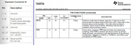
Latelly, I supply the boards individually (from the same PSU) and I have disconnected pins#27,28. See post #37
When I was using EC#1 for distributing power btn the boards, I didn’t have a problem with high frequent noise/hiss.
Check if you have some return current loop issues.
It is Pins 5-20 and 27-28 that I guess need to provide some connection btn boards but I maybe wrong. If you have dedicated supply to the boards, try removing Exp. Conn#1 (with power off ).
The worst that can happen is that the boards will not function.
Report back.
The first configuration of the stack was with the four channels in SE on each miniAMP. I didn’t have turn-off thumbs. But again, I was feeding all the boards from the same PSU.
For no turn-off thumbs to speakers, the power supply voltage at the miniAMP boards should go down at the same time or better, before that of the miniDSP board.
Check if this is the case with your set-up in which you use dedicated PSUs.
Do another test by placing a jumper on MUTE/GND.
George
I was using the Expansion Connector #1 to use the ribbon cable to provide the power to the minidsp, but was not satisfied, caused by residual and remarkable high frequent noise/hiss with the connected speakers.
Latelly, I supply the boards individually (from the same PSU) and I have disconnected pins#27,28. See post #37
When I was using EC#1 for distributing power btn the boards, I didn’t have a problem with high frequent noise/hiss.
Check if you have some return current loop issues.
Have you ever tried, to omit the ribbons for Expansion Connector #1 ?
It is Pins 5-20 and 27-28 that I guess need to provide some connection btn boards but I maybe wrong. If you have dedicated supply to the boards, try removing Exp. Conn#1 (with power off ).
The worst that can happen is that the boards will not function.
Report back.
Can this be a 'discharge' from the coupling capacity in SE mode ?
The first configuration of the stack was with the four channels in SE on each miniAMP. I didn’t have turn-off thumbs. But again, I was feeding all the boards from the same PSU.
For no turn-off thumbs to speakers, the power supply voltage at the miniAMP boards should go down at the same time or better, before that of the miniDSP board.
Check if this is the case with your set-up in which you use dedicated PSUs.
I am already thinking to create a simple circuit, which will pull down the PDN pin on Miniamp to ground, before the power supply capacitors will discharge. But first tests, by placing a jumper on PDN/GND also resulted in big thumbs... So I am asking if anybody has some experience with the logic behind the PDN Pin of the MiniAmps and the power up/power down behavior of the board.
Do another test by placing a jumper on MUTE/GND.
George
Attachments
- Status
- Not open for further replies.