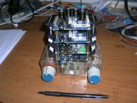
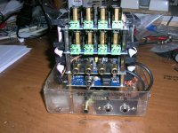
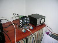

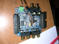
My stack consists of the following boards:
One MiniSTREAMER
One MiniDIGI
One MiniDSP
Two MiniAMP
The miniSTREAMER is connected to the MiniDIGI through it’s SPDIF in/out. It is connected to a PC through the USB port for to receive from (playback) and send to (record) digital music files.
The MiniDIGI has a switch for Analog/Digital Input selection and a four position selector for the digital inputs.
The SPDIF#1in is allocated to the PC, the SPDIF#2 in to the CD transport digital out.
The optical inputs are still free.
The MiniDSP receives digital signals from the MiniDIGI through the I2S lines (ribbon cable) and left/right channel analog through it’s analog RCA inputs.
In these analog inputs I have connected the output of my preamplifier, where the selection of the various analog sources is accomplished.
The MiniDSP has a a single potentiometer volume control, digitally adjusting the four output channels of the MiniDSP.
The controlling software is the 2.1 audio plug-in (stereo mode).
The four I2S outputs feed the two MiniAMP boards through the ribbon cable.
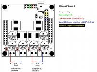
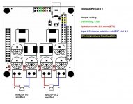
Each MiniAMP board is configured as 2x20W amplifier, -3db input gain.
One board is outputting ch1&2 for feeding two JX92S Jordans omnis.
The other board is outputting ch3&4 for feeding two 12inch KODA woofers in a W frame enclosure.
For now, MiniSTREAMER is powered through the USB port and all the other boards share power via the ribbon interconnect. The PSU is analog 24V/3.5A stabilized and is connected to one of the MiniAMP boards only.
Setting the various jumpers was the hardest part to arrange but it’s all over now. Everything functions properly.
I will provide details for the jumpers and the selectors wiring.
There is no turn-on/turn-off thumb, no input selectors electrical clicks and speakers are dead quiet in idle with any volume setting.
George
One MiniSTREAMER
One MiniDIGI
One MiniDSP
Two MiniAMP
The miniSTREAMER is connected to the MiniDIGI through it’s SPDIF in/out. It is connected to a PC through the USB port for to receive from (playback) and send to (record) digital music files.
The MiniDIGI has a switch for Analog/Digital Input selection and a four position selector for the digital inputs.
The SPDIF#1in is allocated to the PC, the SPDIF#2 in to the CD transport digital out.
The optical inputs are still free.
The MiniDSP receives digital signals from the MiniDIGI through the I2S lines (ribbon cable) and left/right channel analog through it’s analog RCA inputs.
In these analog inputs I have connected the output of my preamplifier, where the selection of the various analog sources is accomplished.
The MiniDSP has a a single potentiometer volume control, digitally adjusting the four output channels of the MiniDSP.
The controlling software is the 2.1 audio plug-in (stereo mode).
The four I2S outputs feed the two MiniAMP boards through the ribbon cable.
Each MiniAMP board is configured as 2x20W amplifier, -3db input gain.
One board is outputting ch1&2 for feeding two JX92S Jordans omnis.
The other board is outputting ch3&4 for feeding two 12inch KODA woofers in a W frame enclosure.
For now, MiniSTREAMER is powered through the USB port and all the other boards share power via the ribbon interconnect. The PSU is analog 24V/3.5A stabilized and is connected to one of the MiniAMP boards only.
Setting the various jumpers was the hardest part to arrange but it’s all over now. Everything functions properly.
I will provide details for the jumpers and the selectors wiring.
There is no turn-on/turn-off thumb, no input selectors electrical clicks and speakers are dead quiet in idle with any volume setting.
George
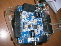
Attachments
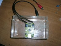

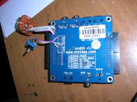


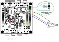

MiniStreamer SPDIG connection to MiniDIGI.
With such a connection, the Master /Slave jumper is non-functional.
I keep the DC jumper closed (in place) because I power the board from the USB connection.
George
With such a connection, the Master /Slave jumper is non-functional.
I keep the DC jumper closed (in place) because I power the board from the USB connection.
George
Attachments
The first objective I had in my mind for my new diy sound system was the requirement for routing to the speakers the signal from any of the sources I have, with a minimum number of signal conversion steps between source and speakers.
The second objective was the minimum disturbance (noise, buzz, ground loops ect ) from the interface of the system components and their interconnects.
These two objectives were achieved by selecting the boards that made this stack.
The third objective was to be able to route any selected signal source to a USB port for the purpose of doing digital recordings with my PC easily and without using an additional signal conversion (soundcard).
This is achieved by routing to the MiniDIGI SPDIF Out the I2S DATA_OUT 7&8.
The MiniDIGI SPDIF Out is rooted to the USB port of the MiniSTREAMER.
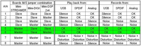
I had a problem with this last step , and I had to look at the issue of the three Master/Slave jumpers present in the boards, in a systematic way.
I made a Truth Table with all the possible M/S jumpers combinations (2^3 =8) and I tested the stack how it behaves in each combination. That is, if every kind of signal source is routed to the speakers and to the recording program in the PC.
You can see the results in the attachment.
There are two jumper combinations (A/A 5 and 6) that work in all cases, noise and distortion free.
There are two jumper combinations (A/A 1 and 2) that work partially.
There are three jumper combinations (A/A 3, 4 and 8) that produce silence or noise.
The jumper combinations A/A 7 produces a mixture of interrupted signal, distortion and noise that is dangerous to the system.
After you will read the table results, you will notice that what I wrote in post #6
George
>Edit: The results of the table hold true for the SPDIF connection between MiniSTREAMER and MiniDIGI.
I don’t know what happens with a I2S connection between these two boards
The second objective was the minimum disturbance (noise, buzz, ground loops ect ) from the interface of the system components and their interconnects.
These two objectives were achieved by selecting the boards that made this stack.
The third objective was to be able to route any selected signal source to a USB port for the purpose of doing digital recordings with my PC easily and without using an additional signal conversion (soundcard).
This is achieved by routing to the MiniDIGI SPDIF Out the I2S DATA_OUT 7&8.
The MiniDIGI SPDIF Out is rooted to the USB port of the MiniSTREAMER.
I had a problem with this last step , and I had to look at the issue of the three Master/Slave jumpers present in the boards, in a systematic way.
I made a Truth Table with all the possible M/S jumpers combinations (2^3 =8) and I tested the stack how it behaves in each combination. That is, if every kind of signal source is routed to the speakers and to the recording program in the PC.
You can see the results in the attachment.
There are two jumper combinations (A/A 5 and 6) that work in all cases, noise and distortion free.
There are two jumper combinations (A/A 1 and 2) that work partially.
There are three jumper combinations (A/A 3, 4 and 8) that produce silence or noise.
The jumper combinations A/A 7 produces a mixture of interrupted signal, distortion and noise that is dangerous to the system.
After you will read the table results, you will notice that what I wrote in post #6
was only partially correct. Sorry for that. I was misleaded too.With such a connection, the (MiniSTREAMER) Master /Slave jumper is non-functional.
George
>Edit: The results of the table hold true for the SPDIF connection between MiniSTREAMER and MiniDIGI.
I don’t know what happens with a I2S connection between these two boards
Attachments
Last edited:
While reading all the boards manuals, I was puzzled as to what the “Data_In” and “Data _Out” mean.
The “In”/”Out” designation is referring to which board exactly ?
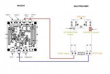
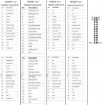
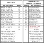
I started looking into this by comparing the pin assignment at the boards expansion slots, through which, the ribbon cable carries the I2S channels along the four boards.
The comparison (see first attachment) brings out some differences among the boards but focusing only on the I2S pins, all expansion slots have the same pin assignment, except for one pin (Pin #12).
Then I started testing the electrical routing between the expansion slot of the Mini DSP board and the pins of the ADAU1701 chip, the heart of the Mini DSP board (see second attachment and http://www.analog.com/static/imported-files/data_sheets/ADAU1701.pdf )
After this test, I was certain that in all the technical manuals of the boards, “I2S_Data_In x&x” means “ADAU1701 SDATA-In x” and “I2S_Data_Out x&x” means “ADAU1701 SDATA-Out x” . Ditto for the BCLK and LRCLK lines.
George
The “In”/”Out” designation is referring to which board exactly ?
I started looking into this by comparing the pin assignment at the boards expansion slots, through which, the ribbon cable carries the I2S channels along the four boards.
The comparison (see first attachment) brings out some differences among the boards but focusing only on the I2S pins, all expansion slots have the same pin assignment, except for one pin (Pin #12).
Then I started testing the electrical routing between the expansion slot of the Mini DSP board and the pins of the ADAU1701 chip, the heart of the Mini DSP board (see second attachment and http://www.analog.com/static/imported-files/data_sheets/ADAU1701.pdf )
After this test, I was certain that in all the technical manuals of the boards, “I2S_Data_In x&x” means “ADAU1701 SDATA-In x” and “I2S_Data_Out x&x” means “ADAU1701 SDATA-Out x” . Ditto for the BCLK and LRCLK lines.
George
Attachments
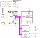
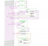
Using the data provided in the 2.1 Plug-in (1st attachment), I drew the “I2S-Data_In” and “I2S_Data_Out” routing channels between the boards(2nd attachment) of my stack.
There are the timing channels as well but writing details over it, is another difficult exercise for me (I don’t know how many drummers are giving the pace, who is playing when and if they are synchronized)
http://www.youtube.com/watch?feature=endscreen&v=abwC5mwlg94&NR=1
George
There are the timing channels as well but writing details over it, is another difficult exercise for me (I don’t know how many drummers are giving the pace, who is playing when and if they are synchronized)
http://www.youtube.com/watch?feature=endscreen&v=abwC5mwlg94&NR=1
George
Attachments

Last edited:
Hi, good job how about the sound? I want to make the same system... is there any problems to stack two amps? Why did you use the usbstreamer of miniDsp? Your comment of the stack is the useful information to me. Thsnks
how about sound quality?
Is there any merit to use the ministreamer instead of usbstreamer?
your detail work diary is very useful information for us
thanks
Hi you made a good job for us who have a interesting about minidsps. How about the sound quality ? Is there any noise? Do you have any problems to make stacks of the miniAmps? How to make the connection among the amps and miniDsp?As you can see, this is a “cost no-object” stack implementation 😀
George
Is there any merit to use the ministreamer instead of usbstreamer?
your detail work diary is very useful information for us
thanks
Sorry for the delayed response
Hi lube2946
Thank you for your kind words about my work diary (my posts are exactly this).
Is there any merit to use the ministreamer instead of usbstreamer?
I haven't tried USBStreamer
For me, MiniStreamer:
- Is cheaper (I am on a tight budget)
- It works without dedicated drivers. Apart from the ease of installation, this makes it certain that it will work on any operating system ( I had a few problems with other drivers when I changed OS).
- In single operation (playback or recording but not both simultaneously) it supports up to 24bit/96KHz. In dual mode (playback and recording simultaneously) it supports up to16-bit/96KHz. My needs are covered as I go for even lower resolution/sampling rates.
I want to make the same system... is there any problems to stack two amps?
If you use the 2way Crossover ADV 2.1 plug-in, the two MiniAMPS will work fine if you place the jumpers as I have shown in post #3. (The 2way plug-in will not work!)
How to make the connection among the amps and miniDSP?
Through the ribbon cables.
I made my own (it takes ribbon, connectors and a vice) but you can ask from MiniDSP devteam to send you two.
For my ears, the only issue was caused by overloading the MiniDSP.How about the sound quality ?
After I paid attention not to overload the MiniDSP and the MiniAMPS (see these two posts: ) the sound is very good for me.
I was really surprised with the -power/sound fidelity- capabilities of the MiniAMPS.
Try them and report back
Is there any noise?
The speakers are dead quiet.
With my ear over them and even at the highest volume setting, I can’t detect any noise.
What I can say from my working with the MiniDSP and other dedicated power amplifiers (class A, AB, D) I have connected them to it, is that in terms of noise, the MiniAMPs win hands down due to their I2S connectivity with the MiniDSP board.
The SPDIF isolation transformers of MiniSTREAMER and MiniDIGI greatly add to the “silence” of the stack.
Tomorrow I hope to be able to show some measurements regarding noise levels.
George
Last edited:
During the course of doing noise level measurement recordings of the MiniSTREAMER-MiniDIGI-MiniDSP part of the stack, I noticed that these recordings showed a peculiarity.
The recorded files are a bit longer in duration and shifted lower in frequency compared to the test signal files fed into the stack.
The test signal files were silent signal and sinusoidal 997Hz tone of various amplitudes made through Audacity sw, at 16/44.1kHz and 16/48kHz.
I burned the16/44.1kHz files into a CD and I used my CD player to feed the stack as an analog signal and as an SPDIF signal.
I fed the 16/48kHz files from my pc through the USB port to the MiniSTREAMER
The playback is true to the fed-in signal. No frequency shift. (I tested it with a frequency meter at the speakers posts)
The problem is on the recording-out side.
The recordings were done by a pc fed from the USB port of the MiniSTREAMER.
Regardless of the input (analog, SPDIF, USB) and regardless of whether the test file is 44.1kHz or 48kHz sampling rate, the recorded file is 1.08846 times longer than the original and the 997Hz test tone is shifted down to 916Hz, that is 0.91873 times (the reciprocal of 1.08846).
I wouldn’t have noticed the time shift but the pitch change is noticeable (In musical terms, it is 1 semitone + 46 cents, almost a tone lower).
I checked the sampling rate of the recordings.
It is the same as the sampling rate of the original test signal files.
And yet these numbers match the 44.1kHz/48 kHz ratio (0.91875).
It seems that a sampling rate conversion takes place somewhere but where?
I tested the two functional combinations of the Master/Slave jumpers of the stack (see post #8):
MiniSTREAMER Master/MiniDIGI Slave/MiniDSP2x4 Master
MiniSTREAMER Master/MiniDIGI Slave/MiniDSP 2x4Slave
Recordings with both combinations have the same problem.
I checked the SPDIF settings on my pc. Nothing there.
I checked the settings of the recording sw. No success.
I did again the recordings with different sw packages (Steinberg Wavelab, Audacity, Wavepad Editor). No luck.
As I am newbie to the digital world, I can’t figure out what else I can do to find the location of the problem and fix it.
I would appreciate a response from any of you who has implemented a MiniSTREAMER/MiniDIGI/MiniDSP2x4 combination and could test the USB rec-out
George
Last edited:
@ George,
I wonder if the issue is simply because you're recording @ 16bit while all our DSP/I2S run @ 24bit. Also note that you should record at the rate of the DSP (48k). A 44.1kHz recording will be an issue.
Also pay attention when you go to 44.1kHz in recording. Sometimes, you may need a reset to actually "reset" to 48kHz the miniStreamer.
Using Audacity you can control all these settings correctly, then make sure that you're playing a 48kH AND recording 48k. (must be in the same clock domain for loopback) You can easily get into a state where you'd believe that you're running @ 48k but indeed Windows didn't reset the USB from an earlier 44.1 test. Just use a scope to double confirm the LRCLK.
DevTeam
Thank you DevTeam for responding.
I am away from home now.
In two weeks I will put my hands over my stack again, so i will try then all what you suggest.
Stupidly enough I haven't tried 24bits, although I still don't think that this is what it causes the issue I have. The rest of your suggestions seem to be closer to it.
George
I am away from home now.
In two weeks I will put my hands over my stack again, so i will try then all what you suggest.
Stupidly enough I haven't tried 24bits, although I still don't think that this is what it causes the issue I have. The rest of your suggestions seem to be closer to it.
George
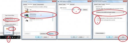
As soon as I returned back home I checked again what is with the recording side of my stack.
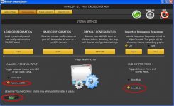
I located the problem on the PC side (Win 7 Home, SP1), at the settings of the SPDIF device.
I attach a pic with the steps I took for proper set-up.
After setting the SPDIF device to 24bits/48kHz, I performed some test recordings which were OK in terms of pitch/duration even when I changed the bit depth/sampling rate (16/44.1k, 24/44.1k, 16/48k, 24/48k) of the recording within the recording software.
So all is well with the stack when recording. Thank you DevTeam
George
Attachments
Last edited:
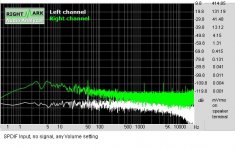
Here are some FFT screenshots from the MiniAmp output of my stack .
Analog input was connected to the analog preamplifier, SPDIF input was connected to the CD player but no signal was applied.
The MiniAmp output signal was picked up from one of the FR speakers terminals through 1.5m twisted wire feeding the primary of a signal transformer (turn ratio1:3.1).
The secondary of the transformer was connected to the input of an Maudio USB Audiophile card.
I used RMAA to do an FFT (size 131072 samples) on the 16/44.1k wav. recordings.
The signal amplitude (mVrms) which I have marked at the right side of the screenshots corresponds to the actual signal at the speaker terminals (and not to the +9.8dB signal at the secondary side of the transformer)
0dB of the soundcard is 1.286Vrms
George
Attachments
-
 SPDIF Input no signal any Volume setting.JPG52 KB · Views: 330
 -
 Analog Input no signal 0% Volume setting.JPG51.1 KB · Views: 308
 -
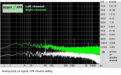 Analog Input, no signal, 10% Volume setting.JPG51.4 KB · Views: 117
 -
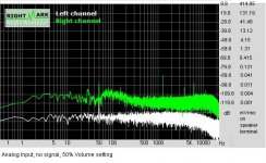 Analog Input no signal 50% Volume setting.JPG52.8 KB · Views: 118
 -
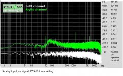 Analog Input, no signal, 75% Volume setting.JPG51.5 KB · Views: 123
 -
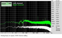 Analog Input, no signal, 100% Volume setting.JPG52.8 KB · Views: 117
Last edited:
Firstly, big thumps up for you! Inspirational!
You said on post #14 "For my ears, the only issue was caused by overloading the MiniDSP.
After I paid attention not to overload the MiniDSP and the MiniAMPS (see these two posts: )", Was it possibly caused by PSU 24v only 3.5 A? miniAmp's manual is suggest 2.5 A for ONE miniAmp. Have ever try to use i.e 24v 5A psu?
- Status
- Not open for further replies.