Hah! Ike Eisenson, circa 1977.
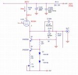
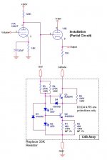
The circuit badly needs a better buffer than an ECC83 CF. An ECC81 with 4-5mA CCS in the cathode circuit (or even a 33k resistor) will greatly improve the HF distortion and slew.
The circuit badly needs a better buffer than an ECC83 CF. An ECC81 with 4-5mA CCS in the cathode circuit (or even a 33k resistor) will greatly improve the HF distortion and slew.
Hello Algar_emi,
Actually, I don´t know. I tested several ECC82 and 5814 and I always got the right voltages give or take 1V. Are you sure that your jumper for the cathode resistor is on the right position?
Kind regards,
Martin
This is my problem, the readings are way off for the last tube., I changed the tube and got the same result. These are ECC82 from Electro-Harmonix. Maybe they don't have the exact specs as the original ECC82. Any suggestion in things I can check?
Actually, I don´t know. I tested several ECC82 and 5814 and I always got the right voltages give or take 1V. Are you sure that your jumper for the cathode resistor is on the right position?
Kind regards,
Martin
Algar, the second would be my preference. Since doing my own buffer preamp, I've given up the adjustability option on the CCS and just set the current approximately with a fixed resistor. You might have to tweak the RIAA values a bit to account for the better source impedance and bandwidth, but the overall distortion will be better and the conformance with tube age and variation will likewise be better.
Looking around to find my problem with the last stage, I was reading in details the 12AU7 specs sheet. One parameter catch my eyes;
Heater negative with respect to cathode, 180V max.
In my case, Vcathode = 260V, and the heaters are only 30V above ground, so I have 260-30 = 230V, way over the maximum 180V.
That may explains some of my problems 🙄
I'll add a 330K resistor in parallel R307 in the supply, to increase the heater offset to about 70V. I'll see if it improve things.
I'll also fine tune the heater supply voltage to 12,6, not 12.2V as now.
According to the schematic you posted earlier, the plate of the driving stage shows as 105V... adding a few volts for the grid bias on the 12AU7 should put the cathode
around 108 volts or so.
Did you check the voltage on driving stage? Grid on the 12AU7? I would suspect either a wiring problem, component value off, or possibly the 12AU7 cathode resistor is open or not connected.
Regards, KM
around 108 volts or so.
Did you check the voltage on driving stage? Grid on the 12AU7? I would suspect either a wiring problem, component value off, or possibly the 12AU7 cathode resistor is open or not connected.
Regards, KM
I'll re-check again, but the circuit tested fine on both sides of the tube.
Thanks for the comments. I'll see what I can do with the grid voltage, maybe add already the grid resistors has suggested by MartinR.
My latest schematic (not the proposed MartinR, that I called ver 2.0) has my actual voltages readings on it. The driving stage cathode is at 112V, not 105V.
Thanks for the comments. I'll see what I can do with the grid voltage, maybe add already the grid resistors has suggested by MartinR.
My latest schematic (not the proposed MartinR, that I called ver 2.0) has my actual voltages readings on it. The driving stage cathode is at 112V, not 105V.
Okay, but the cathode on the follower should only run a few volts higher than the grid... if it's closer to the plate, then it would appear you're not drawing any current thru it, adding resistance between the plate of the driving stage and the grid of the cathode follower won't do anything as the grid does not draw any current. It would appear you have either a wiring error or a bad component.
Regards, KM
Regards, KM
Well, never say never  . What ever the years, you can always do a beginner error
All of you were right. There was missing wires indeed, so the circuit was not working correctly at all...
Wires between V102 anode and V103 grid were not installed, this is why the last stage was way off. Simple error, stupid me
This is what happening when you work on your projects, late at night after a day of work...
I used a variac to reduce the HV supply voltage to what it should be, about 305V, then took the lastest voltage readings. It is making a lot more sense now... Thanks for your help. I just need to fine tune a few resistors to get the correct voltages, add MartinR second RC filter and correct my HV supply CRCRCRC resistors to get the proper HV value.
Now time to test the gain and RIAA response curve.
. What ever the years, you can always do a beginner error All of you were right. There was missing wires indeed, so the circuit was not working correctly at all...
Wires between V102 anode and V103 grid were not installed, this is why the last stage was way off. Simple error, stupid me
This is what happening when you work on your projects, late at night after a day of work...
I used a variac to reduce the HV supply voltage to what it should be, about 305V, then took the lastest voltage readings. It is making a lot more sense now... Thanks for your help. I just need to fine tune a few resistors to get the correct voltages, add MartinR second RC filter and correct my HV supply CRCRCRC resistors to get the proper HV value.
Now time to test the gain and RIAA response curve.
Attachments
...Don't leave me hangin'...
If all goes to plan this may be my first build
get your unimpressed, "what a stupid question" face ready, cuz I'm in way over my head... but i love a challenge.
Frankie.
If all goes to plan this may be my first build
get your unimpressed, "what a stupid question" face ready, cuz I'm in way over my head... but i love a challenge.
Frankie.
I've been looking at the schematic for the EAR... a few more thoughts.
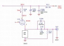
1- The RIAA EQ network works against the 330K plate load resistor in the first stage, not the 2M grid resistor for the second stage (lowest AC impedance). It might make more sense to move the tie point to the plate of the first stage. The 0.15uF cap is still in the loop either way, so it could easily be a moot point.
2- The drive for the RIAA EQ is taken from the output after the coupling cap. You could move the tie point directly to the cathode on the follower and take this capacitor out of the loop. One could argue that having it in the loop is a good thing, but the same could be said the other way. The main difference is voltage across the 330pF cap in the EQ network.
3- The bypass and coupling caps are set for very low frequencies, Typically below 1.5Hz actually. The power supply caps are very large electrolytic types bypassed with low value films. Using better quality film caps and not having paralleled caps might make an improvement. This does become an increase in cost, but I'm just not a fan of paralleled capacitors of dissimilar types.
4- If you don't mind spending the extra $$, the Caddock TF020 resistor is better than the MK132. Using them for other circuit bits like cartridge loading would be an improvement. Again, cost is the largest factor here.
Regards, KM
Wow. This is just beautiful project documentation. Easy enough for a schlemiel like Kofi to follow and build along...
Some questions:
What is the expected overall gain of the design?
Do you think you'll need to use it with a line preamp?
Do you plan to outboard the power supply or keep it in the same enclosure?
Any insight into your grounding scheme you could share?
Kofi
Some questions:
What is the expected overall gain of the design?
Do you think you'll need to use it with a line preamp?
Do you plan to outboard the power supply or keep it in the same enclosure?
Any insight into your grounding scheme you could share?
Kofi
I'll share my info when the come along. I'll try to test it in details within a week. So you'll have the gain, RIAA measured curve, distorsion, etc...
I'll share my ground arrangement (very important) once it is finalized (and I hope quiet).
I won't install a volume control, so I'll need a preamp to use it.
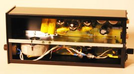
I'm planning to install the preamp and supply into the same enclosure, but I'll test it first. I'll install a metal shield between each section. Since it is a MM stage only, I may be Ok. The original EAR834P is built into the same case (see picture of an upgraded one). I would like a self contained unit easy to install in my rack.
The enclosure I'm planning to use is a recycled Cambridge DVD300 player (now dead). It is a very nice case. I'll scrap the front panel, and replace it with an aluminum plate covered with a nice piece of wood, possibly bird eye maple, or even some exotic wood.
There will be two knobs, power On and mute. I'll add a small PCB with Mute Turn-on timer and mute relay controllable by the front switch.
The final version should use my HV Shunt Regulator PCB to regulate the High Voltage.
I may try SY suggestion of using a CCS in the last section cathode.
Thanks kmaier for all your suggestions. I thought about going all the way with Film caps, but the cost (and size) of these big parts turn me down. If the first result is very good, I may invest in these caps, but first I need to hear it. This is my second tube phono preamp that I'm building and I was not that successful with the first one. I was never able to get ride off a small buzz noise in it (a Cornet Clone)
I may try your suggestion of moving the RIAA point from the output coupling cap though.
Finally, I'm planning to use this preamp with my Thorens TD124, SME3009 tonearm and Shure V15VxMR cartridge. Classic all the way 😀
I'll share my ground arrangement (very important) once it is finalized (and I hope quiet).
I won't install a volume control, so I'll need a preamp to use it.
I'm planning to install the preamp and supply into the same enclosure, but I'll test it first. I'll install a metal shield between each section. Since it is a MM stage only, I may be Ok. The original EAR834P is built into the same case (see picture of an upgraded one). I would like a self contained unit easy to install in my rack.
The enclosure I'm planning to use is a recycled Cambridge DVD300 player (now dead). It is a very nice case. I'll scrap the front panel, and replace it with an aluminum plate covered with a nice piece of wood, possibly bird eye maple, or even some exotic wood.
There will be two knobs, power On and mute. I'll add a small PCB with Mute Turn-on timer and mute relay controllable by the front switch.
The final version should use my HV Shunt Regulator PCB to regulate the High Voltage.
I may try SY suggestion of using a CCS in the last section cathode.
Thanks kmaier for all your suggestions. I thought about going all the way with Film caps, but the cost (and size) of these big parts turn me down. If the first result is very good, I may invest in these caps, but first I need to hear it. This is my second tube phono preamp that I'm building and I was not that successful with the first one. I was never able to get ride off a small buzz noise in it (a Cornet Clone)
I may try your suggestion of moving the RIAA point from the output coupling cap though.
Finally, I'm planning to use this preamp with my Thorens TD124, SME3009 tonearm and Shure V15VxMR cartridge. Classic all the way 😀
Attachments
Hello Kofi,
the gain is supposed to be 52dB. I measured around 54dB. It is enough to drive my power amps (0.5V input sensitivity) with a Benz Glider M (0.8mV output voltage).
My ground scheme is quite simple. Each triode has its own star point with the local gridleak resistor, cathode resistor, and PSU filter cap tied to it. From the local star points goes one wire to the central star point which in this case is the socket of the first tube. The B- is tied to the central star point as well as the heater supply, chassis, and turntable. Even with the power transformer quite close on board, it´s completly hum free on 97dB speakers. The power transformer is a M74 custom wound with about 32W.
Kind regards,
Martin
Martin, when you say the First valve, is it the input 12AX7, or the output one, the cathode follower 12AU7? Thanks....
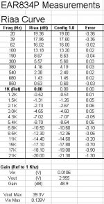
Had a few minutes to take some measurements on my phono preamp.
Riaa curve is almost perfect <1Khz, >1Khz error start to increase at 17Khz. It may be due to my crappy audio generator not been perfectly flat in frequency either. I'm on the road and don't have access to my usual HP test gears. All in all seems to be pretty good.
Gain: 49dB
(lower than 53.2dB of the stock unit, but it may depends on the tubes I'm using at the moment)
Vout max: 39V
Vin max: 0.14V
Check the complete results below.
Attachments
- Home
- Amplifiers
- Tubes / Valves
- My own version of the EAR 834P Clone