Hi again,Hi,
just recognized, that all of my data sheets of drivers are gonsky 🤐
But out of memory I´d say::
- diam: 16-18cm
- fs ~35-40Hz
- Qts ~0.4-0.5
- Qes ~0.45-0.6
- Vas ~20-30L
- Xmax >4mm
jauu
Calvin
I'm still interested in the concept of a dynamic mid-woofer and an electrostatic mid/high panel... My first attempt with four 12" woofers in OB configuration resulted in a good result, but I still prefer the esl full range, without those dynamic drivers.
So now I'm wondering if smaller drivers would make a difference as you wrote they could sound more lively.
I used the parameters mentioned by you to find drivers and was not able to find many. But at least this one looks suitable: (see attachement for datasheet of the 8 ohms version)
SB Acoustics 6” SB17NAC35-8
diam: 14,5 cm
fs: 31,5 Hz
Qts: 0,42
Qes: 0,45
Vas: 33 liters
Xmax: 5,5 mm
I've read some positive reviews about the 4 ohms version of this driver (this 4 ohms model has seems not to have the correct parameters for OB application if I'm correct, Qes=0,34, Qts=0,32)
http://www.troelsgravesen.dk/SBAcoustics-61-NAC.htm
http://www.audioexcite.com/?page_id=5833
But they are not very cheap: 76 euros. I guess I will need at least 7 of them per channel.
Would these drivers be a good and interesting candidate for a open baffle line array mid/woofer to combine with an esl mid/high panel?
Another, cheaper option (30 euros) would be the paper cone SB Acoustiucs 6” SB16PFCR25-8: (for specs see attachement)
SB Acoustiucs 6” SB16PFCR25-8
diam: 14,5 cm
fs: 38 Hz
Qts: 0,40
Qes: 0,48
Vas: 27 liters
Xmax: 4,5 mm
Would this one also be a good candidate and how would it relate to the more expensive aluminium cone one?
Attachments
Last edited:
SB Acoustics 6” SB17NAC35-8 ... I guess I will need at least 7 of them per channel
Even numbers help for arranging suitable impedance eg 3S x 2P (six drivers) = 8.6R. Fed 100W in an OB 42cm wide gives
@kazap: thanks for the quick simulation!
I installed Hornresp myself and I'm reading the manual at https://dokumen.pub/download/hornresp-manual.html and tried to do the same simulation, but I'm not sure if I inserted the correct values. I made some screenshots, maybe you can check / correct my inputs and calculations so I can do some simulations by myself? It seems I can reproduce to get a similar plot.


I installed Hornresp myself and I'm reading the manual at https://dokumen.pub/download/hornresp-manual.html and tried to do the same simulation, but I'm not sure if I inserted the correct values. I made some screenshots, maybe you can check / correct my inputs and calculations so I can do some simulations by myself? It seems I can reproduce to get a similar plot.
- I was unable to find MMd, so I used the MMs value of 15.20.
- I was not sure about S1, baffle area, which unit to use, so I used cm^2: a panel of 20x150 cm equals 3000 cm^2. Not sure if this is correct?
- And how about power, I inserted 100 Watts @ 8 Ohms for Eg. But the driver power rating according to it's datasheet is only 60 Watts? In the third attachement, where I can input Xmax and Pmax, I used 5,5 mm for Xmax and 100 Watt for Pmax. Should Pmax be 60 Watts?
Last edited:
Looks good. I haven't seen a guide for hornresp doing an OB tower. There are a few ways to go so you can play around eg
- for drivers its easier to download the file into hornresp > drivers
- eg http://www.loudspeakerdatabase.com/SB/SB17NAC35#8Ω
- then paste driver
- try setting the OB for just one driver in a square frame eg 20cmx20cm SD=400, so the dipole cancellation is more accurate
- then in Window > 4> Tools > Multiple Speakers
- configure drivers for impedance your amp likes eg class D may like 4R
- then Max SPL enter different W values eg to protect the driver enter the peak power your amp can do and the trasient tolrance of the driver eg 100watts so the cross over prevents bottoming
Hi,
You may have a look at the RS180 series of Dayton.
Similar parameters to the SBacoustics but with slightly more linear stroke and higher Fs, which is good for a small folded OB where the Fb will be a few Hz lower than the Fs.
I haven't experimented with plain OBs but just small compact folded dipoles ... the optimum set of driver parameters will differ between the different OB styles.
The paper cone SB16 shows a similarly raised Fs as the Daytons.
I can't open the data files with my IPad and can't comment in detail ... and in the end You will have to try and test for Yourself if the driver matches the cabinet and Your expectations.
jauu
Calvin
Cms should be 1.68E-03 not 1.68E+00.maybe you can check / correct my inputs
Thanks again for your feedback! I'm still looking for a good manual for Hornresp, for instance, how can I design a square frame? And what kind of baffle shape do I get in my current situation where I only inserted baffle area?Looks good. I haven't seen a guide for hornresp doing an OB tower. There are a few ways to go so you can play around eg
- for drivers its easier to download the file into hornresp > drivers
- eg http://www.loudspeakerdatabase.com/SB/SB17NAC35#8Ω
- then paste driver
- try setting the OB for just one driver in a square frame eg 20cmx20cm SD=400, so the dipole cancellation is more accurate
- then in Window > 4> Tools > Multiple Speakers
- configure drivers for impedance your amp likes eg class D may like 4R
- then Max SPL enter different W values eg to protect the driver enter the peak power your amp can do and the trasient tolrance of the driver eg 100watts so the cross over prevents bottoming
Thanks for the hint! I quess the linear stroke is only .5 mm more (one way), but nonetheless interesting to have alternatives. It seems most drivers don't particularly meet the OB requirements like you mentioned and which are mentioned by M.J. King's "Designing a Passive Two Way Open Baffle Speaker System" which I just started to read, like higher Qt values (1.0 to 1.2) to prevent a falling low frequency response, together with drivers that have higher efficiency (6-10 dB more) than the mid/high (esl) driver to make up for the falling low frequency response.Hi,
You may have a look at the RS180 series of Dayton.
Similar parameters to the SBacoustics but with slightly more linear stroke and higher Fs, which is good for a small folded OB where the Fb will be a few Hz lower than the Fs.
I haven't experimented with plain OBs but just small compact folded dipoles ... the optimum set of driver parameters will differ between the different OB styles.
The paper cone SB16 shows a similarly raised Fs as the Daytons.
I can't open the data files with my IPad and can't comment in detail ... and in the end You will have to try and test for Yourself if the driver matches the cabinet and Your expectations.
jauu
Calvin
Hi,
yes, high Qt drivers show less bass drop than lower Qt drivers.
When testing Ripoles I found drivers with Qts from ~0.6 up to sound more and more boomy and less precise.
A range around 0.35-0.45 seems to be the best compromise with regard to sonical and mechanical behaviour.
You will have to eq drivers with lower Qt electronically though ... a simple bass lift, and even better a high-Q highpass (Subsonic with bass boost) will suffice ... and is a lot more suitable to tune in on Your taste and room requirements.
I'd suggest active xovering with ESLs anyway, since it is so superior to any passive xovered stat.
The bass towers of the my ESLs where eqed down to 35Hz wo subwoofer and only down to 50-55Hz with subwoofer.
The 35Hz limit kept power requirements and the excursions of the drivers to a reasonable safe limit without really limiting the max SPL of the system ... even less limiting when crossing at 50Hz and subwoofer assistence.
jauu
Calvin
When testing Ripoles I found ....
How did you find the ripoles? Did they sound any different to other dipoles?
Thanks for your hint!Cms should be 1.68E-03 not 1.68E+00.
Hi Calvin,Hi,
yes, high Qt drivers show less bass drop than lower Qt drivers.
When testing Ripoles I found drivers with Qts from ~0.6 up to sound more and more boomy and less precise.
A range around 0.35-0.45 seems to be the best compromise with regard to sonical and mechanical behaviour.
You will have to eq drivers with lower Qt electronically though ... a simple bass lift, and even better a high-Q highpass (Subsonic with bass boost) will suffice ... and is a lot more suitable to tune in on Your taste and room requirements.
I'd suggest active xovering with ESLs anyway, since it is so superior to any passive xovered stat.
The bass towers of the my ESLs where eqed down to 35Hz wo subwoofer and only down to 50-55Hz with subwoofer.
The 35Hz limit kept power requirements and the excursions of the drivers to a reasonable safe limit without really limiting the max SPL of the system ... even less limiting when crossing at 50Hz and subwoofer assistence.
jauu
Calvin
thanks again for sharing your valuable experience. This really helps to make it a little easier to hopefully make the right decisions (or at least to not make the worst decisions...)
So I think I will limit my selection to Qts 0.35 - 0.45.
Hi again,
I just played with Hornresp and inserted some drivers. If I'm correct, all 6" drivers are about equal, the Dayton having a bit more Xmax than the SB. I found a 8 inch driver by Dayton as well (DCS205-4) which will go lower in frequency than the 6" drivers. I modeled my Peerless SLS-12 as well.
I inserted 100 Watts max driver input power for max SPL simulations.
Dayton RS180-4:
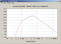
Dayton RS180P-4:
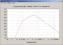
SB17NRX2C35-4:
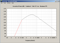
Dayton DCS205-4:
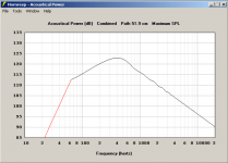
Peerless SLS12:
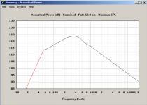
SB17NAC35-8:
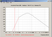
I was wondering if Hornresp simulates both driver + baffle response?
I just played with Hornresp and inserted some drivers. If I'm correct, all 6" drivers are about equal, the Dayton having a bit more Xmax than the SB. I found a 8 inch driver by Dayton as well (DCS205-4) which will go lower in frequency than the 6" drivers. I modeled my Peerless SLS-12 as well.
I inserted 100 Watts max driver input power for max SPL simulations.
Dayton RS180-4:

Dayton RS180P-4:

SB17NRX2C35-4:

Dayton DCS205-4:

Peerless SLS12:

SB17NAC35-8:

I was wondering if Hornresp simulates both driver + baffle response?
I was wondering if Hornresp simulates both driver + baffle response?
Hornresp simulates both driver and baffle dipole cancellation interactions. Thats why you enter both the baffle area in cm2 and the driver specs into the Hornresp config Input Parameters. Hornrep is great for modelling a baffle versus H/U-frame while looking at impulse, impedance, bass extension and Xmax vs freq with watts.
Every sim has limits. Hornresp assumes a circular profile in the Z-axis. So compensate with S selected to reflect the dipole cancellation of your baffle - the "Combined Path". Say you want a 40cm x 200cm flat OB tower with six drivers. You might model a single 40x40cm OB on the floor with eg S=1600 to get the Combined Path you want. Then use the "4. Acoustic Power" panel to add Multiple Speakers. The combined path can stay much the same as the dipole cancellation will take the path of least resistance and stay constant with stacking of the same width baffles. Note the rapidly diminishinga dB increase adding multiple drivers.
The SPL from Hornresp is at one meter. For convincing crescendos you might look at how loud you listen, how many meters back you listen and the transient peaks you need for realism, which can be significant in less compressed orchestral music; while staying safely in the hearing damage guidelines for dB vs time. No point going deaf.
For baffle shape sims look at Edge/Basta
I hope you dont buy 12 drivers straight up when you dont know if its viable. Maybe buy just one or two used drivers first to test and measure.
@kazap: thanks for your message! This clarifies Hornresp a little bit more. But it's still difficult to learn. For instance, I would like to simulate a U shaped baffle as explained in the manual at https://dokumen.pub/download/hornresp-manual.html page 23 "The speaker element in an H shaped Open baffle or a U shaped Open baffle".
Should I use the Input Wizard first? If so, what options should I select? I tried:
1. loudspeaker location: half space (center of floor)
2. loudspeaker type: direct radiator
3. direct radiator loudspeaker type: H-frame open baffle
After this wizard I get back to the input screen and I guess I should input S1, L12 and L56, but L12 and L56 are missing. Am I doiing something wrong?
Yes... Should I use the Input Wizard first? If so, what options should I select?
1. loudspeaker location: half space (center of floor)
2. loudspeaker type: direct radiator
3. direct radiator loudspeaker type: H-frame open baffle
4. Finish
5. Tools > Loudspeaker Wizard> Mask = no> U-frame: S1 = 0 adjust S for woofer size > Save
6. File> Paste driver >calculate
7. Have fun
Last edited:
See https://www.diyaudio.com/community/threads/hornresp.119854/page-637#post-7017598I would like to simulate a U shaped baffle
@kazap and David: thanks again for your help!
Now I have another question: the Schematic DiagramWith acoustic Centers display a Path of 17.1 cm when inserting S1=400 (20x20cm (almost) flat baffle, L12 and L56 0.1:

I searched the manual and the only explanation I can find is:
"The acoustic path length is calculated automatically, and is the length of the shortest
acoustic path between the two acoustic centers in the dipole system. The acoustic
centers are assumed to be point sources."
I'm wondering how this smallest path is calculated? Because I would think the sound has to travel around the baffle which would lead to a larger number?
Now I have another question: the Schematic DiagramWith acoustic Centers display a Path of 17.1 cm when inserting S1=400 (20x20cm (almost) flat baffle, L12 and L56 0.1:
I searched the manual and the only explanation I can find is:
"The acoustic path length is calculated automatically, and is the length of the shortest
acoustic path between the two acoustic centers in the dipole system. The acoustic
centers are assumed to be point sources."
I'm wondering how this smallest path is calculated? Because I would think the sound has to travel around the baffle which would lead to a larger number?
The algorithm used is quite complicated - see the post linked below, and the other posts it references, for further information.I'm wondering how this smallest path is calculated?
https://www.diyaudio.com/community/threads/hornresp.119854/page-523#post-6069923
More references to acoustic centres / centers are given here:
https://audioroundtable.com/forum/index.php?t=msg&th=16472
Last edited:
1. loudspeaker location: half space (center of floor)
2. loudspeaker type: direct radiator
3. direct radiator loudspeaker type: H-frame open baffle
4. Finish
5. Tools > Loudspeaker Wizard> Mask = no> U-frame:S1 = 0adjust S for woofer size > Save
6. File> Paste driver >calculate
7. Have fun
@silvershadelynx
My post above has an error in Step 5. Apologies for my bad edit. It should be:5. Tools > Loudspeaker Wizard> Mask chamber resonance? => no
to bring up:
S1 is the area of the driver baffle in cm2 so set it > Sd of the driver
L12 is the H-frame front extension - slider left for a U-frame
Then check the impulse and group delay and phase of the U-frame vs the OB-planar.
- Home
- Loudspeakers
- Planars & Exotics
- My newest pair of DIY electrostatic panels, advice needed