After reading so much about Tortello's Zen-like headphone amp (I own a Grado headphone too), I decided to try it someday. Then, I got my hand on a very nice enclosure for this project. It was a HP scsi Tape drive. It is build like a tank and the size is just perfect.
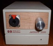
I removed the tape unit and put the Neutrik jack and volume pot on a little maple wood plate. I'll put a piece of aluminium over the HP lettering later. There is an already built-in led. I'll replace it for a blue led.
Thanks Tortello for your nice desing and sharing your PCB's and thanks Mr. Pass for letting us using your ideas.
Here the front panel.
Attachments
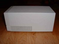
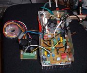
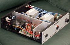
This is a view of the case's inside. It is divided in two main sections. On the back they are already built-in EMI filter, main power switch and a nice little 12Vdc fan running on ball bearings, the HP way 😀
I'll keep the fan running at low speed if I need it. On the bottom I'll mount the 2 channels PCB's. The two IRF610 FET per channel will be mounted directly on the case bottom plate to use as an heatsink. The case has plenty of ventilation in this section that use to have a power supply. The fan is designed to cool this section in particular.
On the top section, I'll mount the EQ-Timer PCB, the Supply PCB and a well shielded toroidal transformer.
I'll mount remotely to the back the DIP switch of the EQ. I already built a small PCB to receive the remote DIP switch.
On the back, I'll install an aluminium plate to cover the two scsi connector mounting holes. I'll install 2 Neutrik RCA output jacks on this plate and the DIP switch.
Attachments

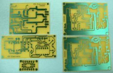
The project wouldn't be complete without some nice PCB's. Tortello did the original desing, Thanks to you. Since I had only the PCB images, I used PaintShop Pro and cut and paste, to do some slight modifications to the PCB's.
I increased all main supplies traces on the Supply and Amplifier PCBs. To the Supply PCB, I replaced the rectifier diodes by bridges, I increased the filering caps to 10,000uF, added the option of adding an other R-C filter to the already built-in C-R-C supply filtering. I plan to remove all supply noises as possible, since headphones are very sensitive. I also added a drop-out voltage resistor and a connector for the fan supply, if needed.
On the Amplifier PCB, I increased power traces width, added an other input cap in parallel (if I want to try different input caps, with or without bypass) and I increased some pads dimensions.
On the EQ-Timer PCB, I increased some pads dimensions, reduced the PCB width (to fit the PCB in the case top section) and added the option fo connect a multipair cable to mount the DIP switch remotely. I did also a small PCB for the switch.
Here the etched PCB before drilling and assembly. I got all the parts in stock and should start to assemble the PCB this week.
Attachments
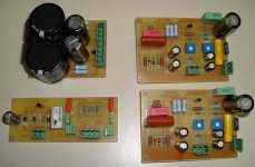
All the PCB are completed and working perfectly.😎
I installed matched IRF610 FET. They are mounted under the amp PCB and will be mounted on the case's bottom plate.
I checked them using a square wave and they seems OK.😀
I'll do measurements in a few days. Here the PCB view.
I installed matched IRF610 FET. They are mounted under the amp PCB and will be mounted on the case's bottom plate.
I checked them using a square wave and they seems OK.😀
I'll do measurements in a few days. Here the PCB view.
Attachments
Thanks for your good words. No listenignsession yet. It is almost 36C these days and I'm spending my days in the pool. I'm working a to mount the PCB in the case for the moment. Maybe, by monday, I'll have some impressions.
First measurements and listening test of my prototype. Sounds superb, big and fast bottom end, sweet hights. The female voice just stand in the air. And this is a brand new one unit, not even burn in. There is no noise in the background with volume at maximum. The CRCR supply filter seems to work Ok.
I'm using rather standard input coupling caps and pot. Input are Panasonic metalized polypropylene (2.5uF) with ERO polycarbonate (1.5uF). Pot is a standard plastic film and output caps are Panasonic FC. I'm using a pair of Grado SR-125. The Equalizer is not connected yet.
Bias is set at 200ma for now. At this bias the FET are at 50 deg C
I'll let it run for the night at that bias, then if it survive, I'll increase to 300ma tomorrow 😉
Here a few measurements (bias 200ma, in 33 ohms load):
Supply Volt (At the amp): 22.2Vdc, ripple 1.5mv
Bandwitdth: 5Hz to 22Khz
Harmonic Distorsion (1Vrms output): 0.3%
😀
So far my first impressions are very good indeed. A very nice little project. I'm feeling I'll like this amp a lot.
Thanks again Marcello Pellerano and Mr. Pass.
Caps do have a sound...
I almost completed the complet assembly of the amp. A few days ago, I completed the supply and transfo mounting. I also installed external wires that connect to the input caps PCB junction points.
Since a week, I'm listening to different coupling caps and, well very interesting discovery. As a lot of you know, caps have sound and I experienced it again.
The pretenders for the best cap were:
-The original cap in the prototype consisting in a 3.0uF, 250V, Polypropylene, Panasonic ECG in parallel with an 1.5uF, 63V, Polycarbonate, ERO MKC1862. Cost: 5.43U$, I had the ERO in stock
-Mundorf M-Cap MKP, two 1.8uF in parallel for 3.6uF, 400V, Cost: 8.50U$ for two.
-Auricap 5.0uF, 200V, correctly connected, output lead is red. Cost: 16.95US ea
-Mundorf M-Cap Supreme, 3.3uF, 800V, Cost 25.90U$ ea, ouch!
Here the listening impressions:
-Panasonic ECG & Polycarbonate, ERO MKC1862: Not very good. Sound without life, my son comments that it sound as cartoon! The worst choice...
-Mundorf M-Cap MKP: The treble killer! The highs are very forward and aggressive. A very brillant cap used in this application. The voices have a lot of grain. Almost a touch of distorsion when voices are on the edge. A listening experience that cause fatigue, not very good either
-Auricap: We are getting there. Good high, fresh presentation, mids with clarity. Bass with impact. Only reservation, very neutral sound, doesn't or improve anything. Pretty good choice in all 😎
And the absolute winner, the Mundorf M-Cap Supreme
Improve on the Auricap in all aspects, with a little smoothness. I like it very much. Only problem, it is big and cost a max! But what a great cap and I guest you get what that you pay for... 😀
So the choice is yours. If you build this amp, USE a very good input coupling cap. It is very important for good results
Bye...
Thanks a lot for your impressions, Algar_emi. Very usefull. Well, I have had my doubts about these MKP's lately! The package is way too touchy! If you measure a MKP cap with your meter and squeeze it a bit, you'll know what I mean. A sturdy housing is better, as I learned from a friend! I have tremendous results with a MKT cap. (BC) Those big MKP's also acts like antennea's, picking up all the noise they can. You might want to try some metalized polyprop's, like these:http://www.elfa.se/pdf/65/06557607.pdf
Or something similar.
Also, they doesnt cost you that much😉
Steen😎
Or something similar.
Also, they doesnt cost you that much😉
Steen😎
I know this is kinda late, but I thought I would share anyway.
I built Marcello's amp as well, and it sounds teriffic once broken in. However, it took significant break-in before it loosened up, became more detailed, and developed the full, warm sound that I had hoped for (i.e. ~75 hours). Marcello and others who have built it seem to agree that break-in is inevitable.
You may want to wait to do extensive testing and part swapping until it's broken in.
Regards,
Bryan
Attachments
Bryan, that amp of yours, wow! Really nice work
IMHO, one of the most beautiful!

Marcello
Yes, I agree, what a beauty. The amp had been running for two weeks, none stop. Each caps was running for 2 days before listening to it.
I agree about mechanical noise in the big caps. I have 4.7uF, MKP WIMA as bypass in one of my amp. At full power, 1khz test tone, the WIMA cap sings at 1Khz!
I'll mount the cap securely. I may also instal copper foil around it.
Thanks...
I agree about mechanical noise in the big caps. I have 4.7uF, MKP WIMA as bypass in one of my amp. At full power, 1khz test tone, the WIMA cap sings at 1Khz!
I'll mount the cap securely. I may also instal copper foil around it.
Thanks...
- Status
- Not open for further replies.
- Home
- Amplifiers
- Pass Labs
- My new ZEN-like headphones amp