Replacement
Hi Al,
I don't if the 2SK117 is also absolete, if available it is a good replacement.
regards,
Piersma
Hi Al,
I don't if the 2SK117 is also absolete, if available it is a good replacement.
regards,
Piersma
Thanks guys for the help.
I checked with Linear Integrated System, the LSK170B/C are in stock and still being manufactured. Thanks Andrew for the tip.
They're not pin compatible with the 2SK170 but rotating Q1&Q2 back to the original orientation is no big deal.
Thanks again,
Al
I checked with Linear Integrated System, the LSK170B/C are in stock and still being manufactured. Thanks Andrew for the tip.
They're not pin compatible with the 2SK170 but rotating Q1&Q2 back to the original orientation is no big deal.
Thanks again,
Al
Last edited:
the LSK range are exactly pin compatible to the equivalent Toshiba device.
The BF244 & BF245 are not pin compatible.
The BF862 cannot be pin pin compatible, it is SMD.
The BF244 & BF245 are not pin compatible.
The BF862 cannot be pin pin compatible, it is SMD.
You're right Andrew, they are pin compatible. Great, I don't have to change anything.
Thanks,
Al
Thanks,
Al
Last edited:
function of D1
Hi Andrew,
You can find D1 in the schematic of Rev_1.4 (on previous page).
Regards,
JohnM
Hi Andrew,
You can find D1 in the schematic of Rev_1.4 (on previous page).
Regards,
JohnM
OK I have one qetion rather stupid I know. I want to do this version of syasym, and trimmer R36 I have to put on minimum resistance or maximum. Before turning up? I presume minimum resistance?
Hi Josip_Del
You need to set R36 to maximum resistance before turning it up.
Regards,
Al
You need to set R36 to maximum resistance before turning it up.
Regards,
Al
Last edited:
I know that I am annoying but I wish to get rid of some stuff that I have. So my last question would be the amp would be based on the schematic V1.3. I am planning to add another par of output devices. Can I use 0.47R 3W on resistors R8 R9 without degrading performance of amp, or to go with original 0.2R?
Hi Al,
Can you explain the function of D1 (1N4148) at the LTP?
Regards,
John
which post?
D1 is not in the first schematic shown at the beginning.
which schematic?Hi Andrew,
You can find D1 in the schematic of Rev_1.4 (on previous page).
Regards,
JohnM
Which post? page before the beginning cannot be searched.
post96 D1 is temperature compensation.
Read the original Symasym paper and subsequent discussions.
Read the original Symasym paper and subsequent discussions.
Function of D1
Hi Andrew,
After some search I found that it's function was indeed meant for temperature compensation (post21 of Roender's RMI-FC100). Thanks for your help.
Although I doubt if this compensation is really needed.
Best regards,
JohnM
Hi Andrew,
After some search I found that it's function was indeed meant for temperature compensation (post21 of Roender's RMI-FC100). Thanks for your help.
Although I doubt if this compensation is really needed.
Best regards,
JohnM
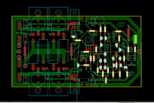
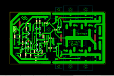
Another option PCB
Yes, i like to design PCB.
My PCB version of AAK's DTV rev_1.4 amp. May single layer PCB, friendly for DIYer.
Not Builded yet! may error, please double check if interest to used it.
PCB files on KICAD format.
Yes, i like to design PCB.
My PCB version of AAK's DTV rev_1.4 amp. May single layer PCB, friendly for DIYer.
Not Builded yet! may error, please double check if interest to used it.
PCB files on KICAD format.
Attachments
5200/1943 bias current
Hi Al/all,
Which bias current would you recommend for each of the 5200/1943 output transistors?
Best regards,
John
Hi Al/all,
Which bias current would you recommend for each of the 5200/1943 output transistors?
Best regards,
John
- Status
- Not open for further replies.
- Home
- Amplifiers
- Solid State
- My new SymAsym PCB design Rev_1.3