 not bad at all. I lot better than most of my P2P type stuff.
hey can u guys please tell me how i can add a simple volume control to this thing
just add a logarithmic potentiometer to the input
logarithmic pot?
so i just put it at the input signal right?
so i put it in parallel with both the left and right channels right?
but isnt that used to adjust the gain?
just a pot right no other components?
so i just put it at the input signal right?
so i put it in parallel with both the left and right channels right?
but isnt that used to adjust the gain?
just a pot right no other components?
Just a pot will get you up and running. 10, 20 or 50k are okay, play around with values, everyone else does 🙂
Source > pot > amp input.
More importantly at the moment are heatsinks! 😉
Source > pot > amp input.
More importantly at the moment are heatsinks! 😉
hey guyss,,,,,,,,
need help i have grounded pin7 of the lm3886 wut do i do with pin 8 (mute pin) do ground directly.
i am using carlosfm's unregulated psu.
below in the notes he has written use 100nf+100uf caps on chips psu pins.
that means i put one pair between +v and ground. and other pair on -v and ground.
but as i am using br100 schematic. do i have to do this to the second chip's psu pins too?
that is total of four pairs?
hey guys come on reply me pleasseeeeeee!!!!!!!!!!!!!!!
ok i have setteled with the mute pin. now i can hear the sound from the amp. it works fine!!!!!!!
but the thing is i have used a 35k resistance between pin 8 and -V. will this reduce the total out put ?
and also the thing is i am not much satisfied with the hi frequencies of the amp. i was expecting more. i have addes a zobel. and used the br100 schm from the an-1192 file without any modifications.
and i am using carlos fm's unregulated psu.
does any one have any suggestions, so that i can get more crystal clean sound. any filters or something like that?(please post a link or schematic)
Attachments
helo guyssssss,
please why isnt any one replying to my posts???
i really need help here. my project has stalled because of no replies
please why isnt any one replying to my posts???
i really need help here. my project has stalled because of no replies
The sound of the amp is what it is, and except if you did something wrong the highs should be crystal clear.
Please add an exact design of the circuit and how you wired it.
What tweeters are you using? Have you tried them with other amplifier and got the highs you wanted? Have you tried different sources?
Are you using any parallel capacitor at the input? Which value?
Carlos
Please add an exact design of the circuit and how you wired it.
What tweeters are you using? Have you tried them with other amplifier and got the highs you wanted? Have you tried different sources?
Are you using any parallel capacitor at the input? Which value?
Carlos
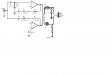
i am using the br100 schematic. and i have just added 2 zobel networks
at the outputs of the two chips on both boards.
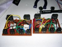
i have done p2p connections. i am using carlosfm's unregulated psu for chipamps. i have also added 100uf + 100nf caps between -v &ground and +v & ground.
i havent added anything at the input. do u think adding caps at the input will help?
actually the highs r good enough but the thing is when i pump the volume the tweeters seem to distort.(i am using sony hifi speakers)
but the thing is the speakers seem to work fine on my 65rms harman/kardon ht receiver.
so is this amp more powerful than my harman/kardon?
at the outputs of the two chips on both boards.
i have done p2p connections. i am using carlosfm's unregulated psu for chipamps. i have also added 100uf + 100nf caps between -v &ground and +v & ground.
i havent added anything at the input. do u think adding caps at the input will help?
actually the highs r good enough but the thing is when i pump the volume the tweeters seem to distort.(i am using sony hifi speakers)
but the thing is the speakers seem to work fine on my 65rms harman/kardon ht receiver.
so is this amp more powerful than my harman/kardon?
Attachments
i am using the br100 schematic. and i have just added 2 zobel networks
at the outputs of the two chips on both boards.
i have done p2p connections. i am using carlosfm's unregulated psu for chipamps. i have also added 100uf + 100nf caps between -v &ground and +v & ground.and also i have added 30kohm resistors accros mute pins instead of 10k
i havent added anything at the input. do u think adding caps at the input will help?
actually the highs r good enough but the thing is when i pump the volume the tweeters seem to distort.(i am using sony hifi speakers)
but the thing is the speakers seem to work fine on my 65rms harman/kardon ht receiver.
so is this amp more powerful than my harman/kardon?
Attachments
as a guess id say no, its probably you amp stage thats running out of power and not your speakers?
might be wrong tho.
might be wrong tho.
sr2002 said:i am using the br100 schematic. and i have just added 2 zobel networks
at the outputs of the two chips on both boards.
i have done p2p connections. i am using carlosfm's unregulated psu for chipamps. i have also added 100uf + 100nf caps between -v &ground and +v & ground.
i havent added anything at the input. do u think adding caps at the input will help?
actually the highs r good enough but the thing is when i pump the volume the tweeters seem to distort.(i am using sony hifi speakers)
but the thing is the speakers seem to work fine on my 65rms harman/kardon ht receiver.
so is this amp more powerful than my harman/kardon?
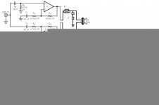
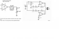
There seems to be some mistake in the way you up-loaded your schematic, because I can see only half of it.
But there's something you should eliminate right away: the zobels. Listen to the amp without the zobels, then with them. And put them BEFORE the output resistor, not after it.
What series resistors are you using at the outputs?
Did you match the resistors to the specified values?
The problem with the specified circuit, IMHO, is that the amps are not exactly the same, but use different gain resistors to compensate for the configurations. Using a transformer or a balancing chip (like DRV134) and matched resistors on the same configuration amps (inverted or non-inverted) would be better.
Using p2p connections on a bridge is not the best option, I think, as there are too many parts and places to do a mistake. A prototype board would have been better.
No, adding caps at the input would not help. But if you did have a parallel cap at the input it might be working as a low-pass filter, and then cutting the highs.
One way to accurately see where your amp's highs are falling is using a 'scope or doing some measurements. Can you do that?
Your amp is a bridge, so it's quite likely more powerful than the HK. If you are using the supply specified in BR100 (+/- 26V) you are delivering 100 watts onto 8 ohms. Your speakers are quite likely less then 8ohm types, so the power delivered may even be larger.
What Sony speakers are you using? Sony is not a speaker manufacturer and, except for some very expensive types released in the '80s, never made decent speakers. There's also a diffrerence between "hi-fi" and high quality, so maybe part of the blame in the sound you are listening to are the speakers.
What I mean is that you may be pushing mediocre tweeters too much, or even endangering their existence.
The next thing that is usually associated with less highs is oscillation. Try to find similar designs to yours in this forum and see what layout they used, particularly grounding. Does the chip heat too much? Is the heat being dissipated onto the heatsink?
Did you measure any offset at the output?
What capacitor types are you using at the input? Bad input capacitors can impair the highs.
Try using 2.2uF or 1uF polyester caps for all of them and see if the highs improve.
Use good quality smaller caps close to the power pins, like 47uF or so.
Carlos
hey thank u very much,
but the thing is i hae hardwired everything together. so like its impossible to take the zobels off. i have attached the pic of my zobel.
and wut exactly is the purpose of a zobel?
i dont understand the thing about gain resisters that u said (i am a newbie) how do u adjust the gain i mean is it really needed?
and probably i think the problem might be with the speakers as u told. i might be pushing then too much.
i am using 25-0 25-0 trafos. after rectification the voltage is 35-0-35v
and 10amps.
do u think i need some fan cooling?
and i am gonna use ganged pot with a resistance in parallel for volume control.
and u didnt tell me about the mute pin? i am using 30k resistors at mute pin. everyone else has used just 10k. does this affect anything.?
i have paralleled 100uf and 100nf caps at the power pins.
and i think i'll test it one more timeto check the highs.
the speakers i am using are regular hi-fi system speakers not actuall good quallity ones. they are rated 85wats rms (which is a fake i know)
Attachments
hey i just checked the an-1192 file. it says that i should use +/-37v for 16ohms load.
and my psu is +/-35 10 amps(5amps on each rail) . but i am using 8ohms speakers
do u think i should drop the voltage?
how do i do that?
or maybe can i add a resistance at the input? wut value?
i also wanted to add a led can u tell me wut values of resistance should i use for the led
and my psu is +/-35 10 amps(5amps on each rail) . but i am using 8ohms speakers
do u think i should drop the voltage?
how do i do that?
or maybe can i add a resistance at the input? wut value?
i also wanted to add a led can u tell me wut values of resistance should i use for the led
sr2002 said:
but the thing is i hae hardwired everything together. so like its impossible to take the zobels off. i have attached the pic of my zobel.
and wut exactly is the purpose of a zobel?
The zobel is a specific application low-pass filter.
Why is it impossible to take the zobels off if it's hardwired p2p? Then your arrangement is being just the opposite a p2p design should be: easy to modify.
Do try to take the zobels off because I think that might be the trouble you are having.
i dont understand the thing about gain resisters that u said (i am a newbie) how do u adjust the gain i mean is it really needed?
If you are a newbie then you should have done things exactly as on the National's application note, and not modifying it as your drawing shows. That is adding series resistors and zobels. National did not put any zobel on their design. Take them out.
The gain resistors are those setting the gain in the amplifiers: Ri1/Rf1, Ri2/Rf2. What values did you use there? Did you check the values?
and probably i think the problem might be with the speakers as u told. i might be pushing then too much.
i am using 25-0 25-0 trafos. after rectification the voltage is 35-0-35v and 10amps.
do u think i need some fan cooling?
Yes, that kind of voltage is a bit much for a bridged amp, particularly if the speakers are not real 8 ohms types, which they probably aren't. You might be pusshing the speakers too much.
To see if you need fan-cooling you have to feel how hot the heatsinks are. Also check if the chip is too hot to touch. If you can't hold your finger on it because it's too hot, then you need more heatsinking or chip/heatsink contact is not good. A heatsink should be warm to touch.
and u didnt tell me about the mute pin? i am using 30k resistors at mute pin. everyone else has used just 10k. does this affect anything.?
That value is fine. Don't worry. I would use a value like 22K though. But didn't you say things are difficult to change in your design?...
sr2002 said:hey i just checked the an-1192 file. it says that i should use +/-37v for 16ohms load.
and my psu is +/-35 10 amps(5amps on each rail) . but i am using 8ohms speakers
do u think i should drop the voltage?
how do i do that?
or maybe can i add a resistance at the input? wut value?
i also wanted to add a led can u tell me wut values of resistance should i use for the led
Adding a LED is fine. Use a series resistor, like 4K7 or so, and watch the polarity.
Disregard that 16ohms load info: your speakers are 8 ohm or less, so you need less voltage.
The only way to drop the voltage properly is to use regulators, which I wouldn't advise if you are a newbie.
Just do not push your speakers too much and watch how hot the amp gets (chip and heatsink).
Carlos
Resistor for the led:
R=(U-1,7)/0,012, where U is the value of the voltage where attach the led. The power of resistor must be at least 0,5W.
R=(U-1,7)/0,012, where U is the value of the voltage where attach the led. The power of resistor must be at least 0,5W.
is it ok if i put the led between +30v and ground with a series resistor of 4.7k?
and as drbobee said i should use a 0.5watt resistor right?
i have used Rf as 47k for one chip and 51k for the other.
and Ri is 4.7k.
and i also wanted to ask that, this is a 2 channel amp. that is i have made 2 such boards out of 4 lm3886. so i should connect these in paralell with the psu right?
and as drbobee said i should use a 0.5watt resistor right?
i have used Rf as 47k for one chip and 51k for the other.
and Ri is 4.7k.
and i also wanted to ask that, this is a 2 channel amp. that is i have made 2 such boards out of 4 lm3886. so i should connect these in paralell with the psu right?
sr2002 said:is it ok if i put the led between +30v and ground with a series resistor of 4.7k?
and as drbobee said i should use a 0.5watt resistor right?
i have used Rf as 47k for one chip and 51k for the other.
and Ri is 4.7k.
and i also wanted to ask that, this is a 2 channel amp. that is i have made 2 such boards out of 4 lm3886. so i should connect these in paralell with the psu right?
I should put the LED between +/-30V, to see if both sides of the supply are working. Then your resistor should stand 2 watts (will dissipate slightly more than 1 watt, but it can get too hot). Or use two LEDs for each side, each .5 watt.
The BR300 specifies a 51K1 1% resistor. Did you check the resistors values? When you are bridging or paralleling amps you should be more careful than when building single amps. Resistors should be 1% but matched if equal or checked if unequal, as on Rf2.
Also check the Rb value.
Carlos
hey it workssssssssssssssss!!!!!!!!!!!!!.
it finally came alive on both the channels.
the highs are crystal clear since removed the zobels.
hey but the thing is it is getting a bit hotter than before.
is that because this time i am using both the channels in paralell with the trafo.? because the resistance must have reduced because of the parallel combination.
the trafo. is also getting hot. i am plannin to use a 12v fan. the fan is rated 2.2w and 12v. so can u tell me the value of resistance that i should use? then i will connect the fan with a series resister to the +30 rail and ground.
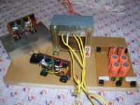
but wut i dont understand is that my heatsinks are facing outwards that is they their fins are outside the box. and the trafo. is inside the box. so i cant practically cool 2 heatsinks on two opposite sides, than i will need 2 fans which in not possible.
so like if i put a fan it will on cool the trafo. so will coolin the trafo help much?
it finally came alive on both the channels.
the highs are crystal clear since removed the zobels.
hey but the thing is it is getting a bit hotter than before.
is that because this time i am using both the channels in paralell with the trafo.? because the resistance must have reduced because of the parallel combination.
the trafo. is also getting hot. i am plannin to use a 12v fan. the fan is rated 2.2w and 12v. so can u tell me the value of resistance that i should use? then i will connect the fan with a series resister to the +30 rail and ground.
but wut i dont understand is that my heatsinks are facing outwards that is they their fins are outside the box. and the trafo. is inside the box. so i cant practically cool 2 heatsinks on two opposite sides, than i will need 2 fans which in not possible.
so like if i put a fan it will on cool the trafo. so will coolin the trafo help much?
- Status
- Not open for further replies.
- Home
- Amplifiers
- Chip Amps
- my new lm3886 amp!!!!!!!