Thanks.It's good to know that someone -besides me- likes it too!
Of course it is one thing to design it and another thing to execute correctly ...
Of course it is one thing to design it and another thing to execute correctly ...
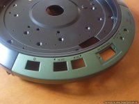
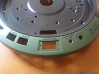
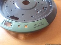
At last, after a month or so i received a call from the silk-screening shop saying that the letters have been printed.
I flew there to see the outcome.
All looked nice and i was happy with the quality of what i saw.
They told me that because of the complexity of the surface they had to do it in three
separate stages...one each for the left, central, and right side of the fascia.
Now that i have it in my hands it's time for the final assembly of the hardware.
After that i have to do the revision of the power supply and i'm done.
See pics:
Attachments
At last, after a month or so i received a call from the silk-screening shop saying that the letters have been printed.
I flew there to see the outcome.
All looked nice and i was happy with the quality of what i saw.
They told me that because of the complexity of the surface they had to do it in three
separate stages...one each for the left, central, and right side of the fascia.
Now that i have it in my hands it's time for the final assembly of the hardware.
After that i have to do the revision of the power supply and i'm done.
See pics:
The font in the pdf seems fine. I would have had a hard time picking one because so many would work for me, at least.
The actual job.
I think I see an out-of-square " auto/manual ".
And the "SoundofVoid" looks like it has an "l" instead of an "i" in void. Probably just the way the ink flows. The font proof in the pdf showed a very narrow gap at the dot over the "i".
But I'm guessing the do-over would cost unwelcome time and work.
-Steve
Yes,it is not perfect...i know!
As i mentioned before i will try to make it CNC engraved next time.
If it is not doable i will remedy all little mistakes on next printing.
It is magnitudes better to work on a given base.
I have been told that it was very difficult and it had to go into the printing stage and next into the oven three times.
I was given the impression that they would not be happy doing it again...
Yes,it is not perfect...i know!
I have been told that it was very difficult and it had to go into the printing stage and next into the oven three times.
I was given the impression that they would not be happy doing it again...
Yes. This indicates the type of work is outside their "comfort zone". And, likely, they can make a living doing other types of work...so....🙄
It would be interesting to know how those Denon people did this task. I'm guessing elaborate dedicated custom tooling specific to the task.
re: other methods. I guess the success of the cnc method, which could be really cool, depends on how small the cutter can be ground and what kind of cutter life can be expected. I'd imagine the plan is to fill the depressions of the cut text with paint, then , after dried, polish the upper surface to clear away the overflow.
-Steve
That is thought...filling up the engravings with paint, wipe of the excess and apply clear coat to seal it in.
But it happens that i even like the plain jane version of just engraved and painted metal with the base color.
The lighter color makes it pretty readable.
This is clearly shown in the PS faceplate.
It is just a matter of getting so small letters...
But it happens that i even like the plain jane version of just engraved and painted metal with the base color.
The lighter color makes it pretty readable.
This is clearly shown in the PS faceplate.
It is just a matter of getting so small letters...
New stuff coming in...
From a shop specialized in vintage camera repairs i have received a special tight-woven type of self adhesive felt used to light-seal the backs of cameras.
I was shopping for a thin type (1.5mm thickness max) as i had my calculations made for a
1.5 gap between periphery ring and extra platter.
I knew paint was going to reduce this but hopped for a tight fit so that the periphery ring would self-center around the platter.
I tried with a 4 points felt pcs and felt it could be a little tighter.
I tried then with 8 and it was a dream.
It would fit snugly and when rotating there was not at all "play"...better than i hoped for!
I have also received thin natural rubber sheets of low Shore grade (about 45) in thicknesses of 1-1.5-2 mm.
Using a modified tool that was originally made for cutting round holes in plaster boards
-now equipped with a very fine scalpel instead of a pizza-wheel- i have cut the round pieces that i wanted to glue under the extra platter and the record weight.
I am veeery happy with the result!
Last i had given a final once over -with a spatula- to the tar like stuff under the original chassis.
It will be left to dry for a couple days and then i can work on it again.
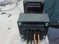
Finally i have been informed that my two oversized transformers will be ready at the end of the week.
Can't wait!
From a shop specialized in vintage camera repairs i have received a special tight-woven type of self adhesive felt used to light-seal the backs of cameras.
I was shopping for a thin type (1.5mm thickness max) as i had my calculations made for a
1.5 gap between periphery ring and extra platter.
I knew paint was going to reduce this but hopped for a tight fit so that the periphery ring would self-center around the platter.
I tried with a 4 points felt pcs and felt it could be a little tighter.
I tried then with 8 and it was a dream.
It would fit snugly and when rotating there was not at all "play"...better than i hoped for!
I have also received thin natural rubber sheets of low Shore grade (about 45) in thicknesses of 1-1.5-2 mm.
Using a modified tool that was originally made for cutting round holes in plaster boards
-now equipped with a very fine scalpel instead of a pizza-wheel- i have cut the round pieces that i wanted to glue under the extra platter and the record weight.
I am veeery happy with the result!
Last i had given a final once over -with a spatula- to the tar like stuff under the original chassis.
It will be left to dry for a couple days and then i can work on it again.
Finally i have been informed that my two oversized transformers will be ready at the end of the week.
Can't wait!
Attachments
-
 Photo0657-Optimized.jpg120.8 KB · Views: 167
 -
 Photo0663-Optimized.jpg46.1 KB · Views: 148
 -
 Photo0662-Optimized.jpg53.2 KB · Views: 137
 -
 Photo0661-Optimized.jpg61.9 KB · Views: 145
 -
 Photo0658-Optimized.jpg65.4 KB · Views: 140
 -
 Photo0665-Optimized.jpg80 KB · Views: 330
 -
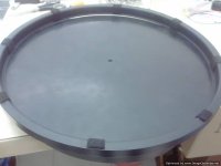 Photo0664-Optimized.jpg44.4 KB · Views: 337
Last edited:
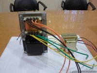
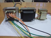
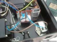
After a redesign of the main transformer (doubled all the mA of the output windings plus a new winding able to power some leds) i have just received them both.
One is an 80 Watts down converter transformer (from 240VAC to 100VAC) and the other is a double sized main transformer.
I have ample space in my power supply box and they will fit in nicely.
I have decided to use this layout instead of a single transformer because i wanted to add another level of separation from AC grid fluctuations.
See pics of them in comparison with the original one.
I think i can see the light at the end of the tunnel...
Attachments
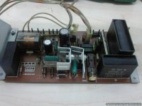
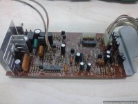
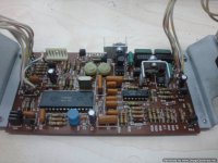
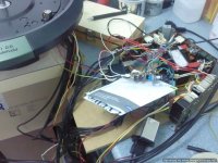
I have done some work on the boards themselves.
I had to have the AC power Hz selector on top and that meant a flip-over on all boards.
New places had to be drilled to have them standing instead of hanging.
New capacitors with increased uf on major reservoir, bypass ones on strategic points and new transistors able to give a bit more juice.
I had to add cooling to them but that was easy.
See the boards in their final state.
Attachments
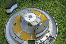
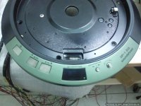
I moved forward to assembly.
I have made the cutout on paper and have cut the bitumine self adhesive sheet
to fit each compartment under the original chassis.
By placing two sheets one on top of other i have managed a 3+mm hight so that
the silencer blocks would compress it to 3mm when screwed in place.
Step by step i screwed them in place.
The damping they provide is enormous.
Plus they will provide a "wall" for placing a soft compression material between them and the metal "bowl" that covers the underside.
Then i placed the top sheet metal that is there to block any magnetism from reaching the platter.
Under this i had already placed a sheet of bitumine and have drilled and tapped
many screw positions around it so it would fit tightly.
On finger tapping a completely dead "thud" is felt -instead of heard- from the whole construction.
I am very pleased so far.
Attachments
-
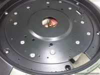 Photo0708-Optimized.jpg66.7 KB · Views: 137
 -
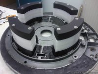 Photo0704-Optimized.jpg100.4 KB · Views: 381
 -
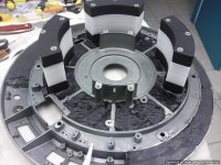 Photo0703-Optimized.jpg121.7 KB · Views: 396
 -
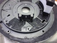 Photo0700-Optimized.jpg143.8 KB · Views: 386
 -
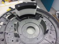 Photo0698-Optimized.jpg112.3 KB · Views: 389
 -
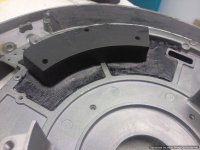 Photo0696-Optimized.jpg105.5 KB · Views: 383
 -
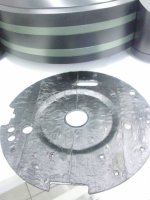 Photo0621-Optimized.jpg60.6 KB · Views: 125
 -
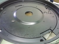 Photo0709-Optimized.jpg82.9 KB · Views: 120
Last edited:

Bravo Martin!
You have chosen to use the same damping technique.
Maybe i should patent this...
What substance is the yellow layer?It is much better if it's just a bit taller than the metal ribs and is compressed to their level by the
silencer blocks...you get the best result this way
You should try pouring a damping agent in the big empty peripheral cavity.
Ask the people that do car stereo installations.They spray into doors a damping agent that you could use...or if you want to really mess with it,
use the tar like substance i used.
Yes...time is an issue with these things...
Keep on the good work and share your results!
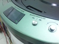
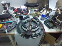
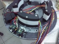
In the meantime i have progressed a bit more.
I have thought about making the buttons black but finally decided
to "smoke" them -spray them with black paint from a distance- and clear coat them.
I don't know if it shows well in the pics -flash kills the subtle hues- but it does look pretty good.
I also added a green led at the side of the stroboscope screen to confirm the
"power on" status.
The turntable in it's original form shows nothing about this and you have to press the 33 or 45 button for it to come in life.
Now when it's on, there will be two leds on : one on the faceplate of the power supply and one on the turntable.
I have also done some work on the transformers regarding shielding.
I think they look great.
Next is the work on the power supply.
I am getting there...
You have chosen to use the same damping technique.
Maybe i should patent this...
What substance is the yellow layer?It is much better if it's just a bit taller than the metal ribs and is compressed to their level by the
silencer blocks...you get the best result this way
You should try pouring a damping agent in the big empty peripheral cavity.
Ask the people that do car stereo installations.They spray into doors a damping agent that you could use...or if you want to really mess with it,
use the tar like substance i used.
Yes...time is an issue with these things...
Keep on the good work and share your results!
In the meantime i have progressed a bit more.
I have thought about making the buttons black but finally decided
to "smoke" them -spray them with black paint from a distance- and clear coat them.
I don't know if it shows well in the pics -flash kills the subtle hues- but it does look pretty good.
I also added a green led at the side of the stroboscope screen to confirm the
"power on" status.
The turntable in it's original form shows nothing about this and you have to press the 33 or 45 button for it to come in life.
Now when it's on, there will be two leds on : one on the faceplate of the power supply and one on the turntable.
I have also done some work on the transformers regarding shielding.
I think they look great.
Next is the work on the power supply.
I am getting there...
Attachments


Last edited:
I used the damping sheets from a local source V E S T I N - izolaèní materiály s.r.o. - AMS-Tecsound bit more power I could use .. Further work on the control will follow. Thanks for consultation.
News on the project...
The mechanics are all done but once more the electronics give me nightmares...
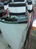
I have used an 1.5 meters 28 cables loom from turntable to the power supply but i have big problems with the motor control.
My tech says that it's too much cable that weakens the signal from the tape head and messes up the sync.
I am building a tape head signal booster to see if this solves the problem.
If this doesn't help i will start cutting cable length to see where it all comes together.
I really want to keep the full blown external power supply.
Otherwise it would be a walk in the park...
The mechanics are all done but once more the electronics give me nightmares...
I have used an 1.5 meters 28 cables loom from turntable to the power supply but i have big problems with the motor control.
My tech says that it's too much cable that weakens the signal from the tape head and messes up the sync.
I am building a tape head signal booster to see if this solves the problem.
If this doesn't help i will start cutting cable length to see where it all comes together.
I really want to keep the full blown external power supply.
Otherwise it would be a walk in the park...
Attachments
Use shielded low capacitance cable for the sensor, see what that does.. Do you have an oscilloscope?
Kevin, i have not been "cheap" on that.
I hate cheap.
I always criticize cheap parts on expensive products and i would't do that in my pride and joy!
I am using Van den Hul's D-501 phono/microphone cable.
It's the standard hook up cable for SME V arm to phono stage.
Specs are here : Van Den Hul - D - 501 HYBRID (Halogen Free)* | Product (cable)
At the moment i will take everything off the prepared sample and will load everything on a test mule.
I cannot risk a scratch on the finished chassis.
For the moment i have a more detailed plan:
I will put my PS right next to the turntable and will start with original cables or slightly elongated ones.
If everything looks good, i will use gradually longer loom to find where -and in what cable-
my problem starts.
When i will have zeroed on the suspect part i will see what can be done to overcome the problem.
At the moment the No1 suspect is the tape head loom.
I will start with all the others long and this in original form to see if the problem stays.
I will keep my fingers crossed!
It's been some time without news on the project...i know...i'm sorry!
What happened is summer vacations and a lumbago...you know from what!
I am waiting for a specialized cable (Datacable Kat. 7 S/FTP 8P AWG23 900MHz Duplex) that has multiple wires, a little thicker than 24AWG originals, screened in groups.
It may help me to solve my locking-to-speed problem.
The courier said it's gonna be here early next week.
I'll have to rip out most of the cables and reconnect with the new one.
Not looking forward to it but it has to be done.
We'll see what happens.
I'll keep my fingers crossed...otherwise i'll have to rethink the whole power supply thing
and that is surely something i am not looking forward to!
Attachments

This a very beautiful turntable you are creating! Do you have a gallery of photos of your other builds?
I don't have a gallery...i'm sorry.
I work with anything that falls in my hands, amps,speakers, digital, tubes (even my car hasn't escaped my twisted intentions )...but my love of anything mechanical, led my efforts mostly to analog...and luckily enough people like it so that my passion stays fuelled.
You can see another effort in "Monsterizing a Dp-80'' and another in "My last turntable".
I have also worked in an SP-10MKII and other DPs.
Unfortunately a great deal of pics was lost when a cellphone was stolen from my gym locker some years ago...
Last edited:
- Status
- Not open for further replies.
- Home
- Source & Line
- Analogue Source
- My new effort on making the ultimate DP-80