Your project is very inspiring, thanks for sharing.
From following this thread I have got the feeling that you miss feedback on your posts. I have resisted commenting so far, to not clutter the thread with a fan-post with no relevant technical or design feedback. Because those +1 and "Great" posts are really annoying when you subscribe to a lot of threads. I think a lot of other members act the same. Your thread is one of those threads where I actually miss a function like the Facebook "Like". Anyway, you can be sure that there are thousands of DIYers who have read and been awed by your efforts.
Regarding the lettering, to be up to the standards of the rest of the project, my view is that the line of letters should be following the diameter of the chassis. At least whith your rather large letters it looks a little awkward with the different texts following their separate baselines.
As to printing on metal, a friend of mine has such a printer which he used to print on mostly flat surfaces. If I recall correctly he had some software where he could compensate for angled surfaces and also to print along the perimeter of a circle.
Last edited:
You're right Naturlyd.
I do miss feedback form viewers.
Maybe it's my style of writing, me looking too sure about where this project is going,
or the fact that i am doing extensive (and expensive!) work on already perfectly good turntables that is putting people off?
I don't know...but making just another wooden plinth wasn't cutting it for me any more...been there, done that.
In another site when i revealed my plan to mix in a heavy duty chassis the motor/platter part from a Pioneer Exclusive TT with the tangential tonearm part from a Pioneer PL-L1
(both very rare and expensive) more or less people accused me of sacrilege...whereas i was thinking of an Ultra Pioneer...a homage!
Anyway...thanks a lot you for your input.
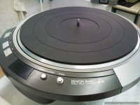
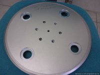
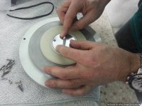
I do know that the printing is not as perfect as it should be.
I chose letters just one mm bigger than original in order to show the difference in the letter styling (that i like very much).
And because in preparation i filled up a line that was casted just above the
buttons now i had much more space and the old lettering looked too small.
What they did was printing the letters in three stages (left -center-right) trying to follow the roundness of the chassis.
That is three times printing and three times "baking" the paint in an oven to harden it.
I will not go this road again.
I 've come to understand that for almost everything i ask from others to do
their understanding of the word "perfect" is different from mine.
But unfortunately i cannot do it all by myself!
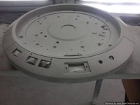
I will use CNC engraving from now on...IF i keep using the original top part.
If the problem with controls/sync persists i am thinking about moving all buttons on the power supply, meaning i will have to cut me another top part.
Difficult, but with one stroke i will be able to solve many problems regarding appearance, damping properties and final presentation.
From the whole DP then i will keep just the motor and the lower platter.
All the rest will be my doing.
I do miss feedback form viewers.
Maybe it's my style of writing, me looking too sure about where this project is going,
or the fact that i am doing extensive (and expensive!) work on already perfectly good turntables that is putting people off?
I don't know...but making just another wooden plinth wasn't cutting it for me any more...been there, done that.
In another site when i revealed my plan to mix in a heavy duty chassis the motor/platter part from a Pioneer Exclusive TT with the tangential tonearm part from a Pioneer PL-L1
(both very rare and expensive) more or less people accused me of sacrilege...whereas i was thinking of an Ultra Pioneer...a homage!
Anyway...thanks a lot you for your input.
I do know that the printing is not as perfect as it should be.
I chose letters just one mm bigger than original in order to show the difference in the letter styling (that i like very much).
And because in preparation i filled up a line that was casted just above the
buttons now i had much more space and the old lettering looked too small.
What they did was printing the letters in three stages (left -center-right) trying to follow the roundness of the chassis.
That is three times printing and three times "baking" the paint in an oven to harden it.
I will not go this road again.
I 've come to understand that for almost everything i ask from others to do
their understanding of the word "perfect" is different from mine.
But unfortunately i cannot do it all by myself!
I will use CNC engraving from now on...IF i keep using the original top part.
If the problem with controls/sync persists i am thinking about moving all buttons on the power supply, meaning i will have to cut me another top part.
Difficult, but with one stroke i will be able to solve many problems regarding appearance, damping properties and final presentation.
From the whole DP then i will keep just the motor and the lower platter.
All the rest will be my doing.
Attachments


You can see another effort in "Monsterizing a DP-80'' and another in "My last turntable."
I just checked them out. Wow! You're a monster!
Thanks for the heads up!
PS, For those interested, click on the red links.

Thanks Budgie.
I have also started working on the Pioneer project that i have mentioned but this will be a slow progress.
The DP gets first dibs right for now because it's on order...and because there is a market opening...
If i get it right, it will be used as a demo in the company of very expensive equipment ($$$$$...worth)
The Pioneer will be an one off, for my personal collection...
It works with magnetic induction on both platter and tangential arm...plus i want to magnetically lighten (not to the point of levitation) the new very heavy "sandwich" platter.
Very difficult to implement and i don't want mistakes with such expensive and rare specimens.
But i suspect this will be the subject of another thread sometime in the future...
Attachments
Last edited:
Both are "Japanese only" products.
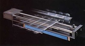
The Darth Vader is the PL-L1 that has an exquisite parallel tracking mechanism
that works without gears belts or strings...just with magnetic induction!
It's the big daddy of the PL-L1000...only executed in true high end spirit.
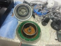
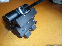
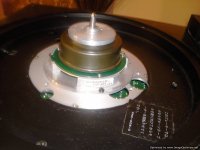
The other part is a stand alone (no arm-like the DP-80) transport with the motor and platter of the legendary P-3.
Ripping the arm and relative mechanisms from the PL-L1 and attaching them to the rest (in the same type of construction that i use here) plus magnetically levitating the new extra heavy platter has been a fixation to me for a couple years...
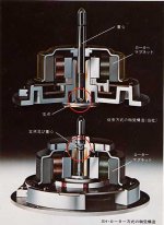
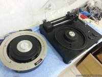
The motor is monumental.You can see the two motors in comparison in the 4rth picture.The central black part in the transport is corresponding to the little protruding part in the center of the PL-L1!
It can move mountains.
The Darth Vader is the PL-L1 that has an exquisite parallel tracking mechanism
that works without gears belts or strings...just with magnetic induction!
It's the big daddy of the PL-L1000...only executed in true high end spirit.
The other part is a stand alone (no arm-like the DP-80) transport with the motor and platter of the legendary P-3.
Ripping the arm and relative mechanisms from the PL-L1 and attaching them to the rest (in the same type of construction that i use here) plus magnetically levitating the new extra heavy platter has been a fixation to me for a couple years...
The motor is monumental.You can see the two motors in comparison in the 4rth picture.The central black part in the transport is corresponding to the little protruding part in the center of the PL-L1!
It can move mountains.
Attachments

Me too!
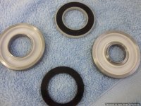
I have designed the new platter (a mix of the old aluminium one and a new bronze part-about 15 kilos in total), the placing and carriers for the opposing magnets (i have custom ordered the N45 magnets-13.5 kilos opposing power),
i have prepped the old platter to accept the new parts and have done a study about the damping materials and where to use them...
The main chassis will be a derivative of the one used here and i need to
make a big chassis to place the arm and it's bits and bolts.
But i need a multiple "me" to tackle all these at the same time...
On with the DP now.
I have arranged to take it to someone who has an oscilloscope to take some measurements and see if if there is a remedy for the electronic quirks...
I went for shopping and have amassed about 5 different cables (thickness-resistance-inductance-shielding and so on) to make the swap on the spot.
If it doesn't work i will have to abandon the "all boards out" scheme and just
keep the heavy vibrating parts out of the main chassis.
I don't want to, but at the moment time is pressing.
I can't seem to receive any notifications to update my knowledge of your progress. 
I feel that the Stable Hanging Rotor motors in the Pioneer/Exclusive turntables to be the most advanced direct drive motors ever made by the Japanese. I would suggest that you consider a panzerholz plinth for the Pioneer P10 motor.
My experiments with cup and ball horizontal isolation in combination with mag-lev have ascertained that the cup and balls need to be arranged equidistant from the center of mass and that the mag-lev footers are best used in a circular arrangement with the load in the exact center(again, with regard to the c-o-m).
The performance of a high quality direct drive/cup and ball/mag-lev collaboration is a tour de force.
Hi Theophile!
No maglev footers! Just opposing ring magnets at the spindle.
My aim is an actual weight on thrust plate of around 1.5 Kg from a total mass of around 15 Kg.
I aim at less drag and friction and even better speed stability.
If i ever think about magleving the whole thing it would be best to do it on a separate supporting surface.
Yes it will be a tour de force...at least that's how i imagine it.
Today is a crucial day.
All afternoon i will be checking the connection/umbilical with different cables with an
oscilloscope.
If it doesn't work i will have to put some boards back into the chassis and make a smaller power supply box with just the transformers and the filtering...
Moon audio has a mag lev platform video that looks interesting.
The only fly in the ointment is the 2 vertical alignment rods to keep it from flying off into space. 🙂
Regards
David
The only fly in the ointment is the 2 vertical alignment rods to keep it from flying off into space. 🙂
Regards
David
Moon audio has a mag lev platform video that looks interesting.
The only fly in the ointment is the 2 vertical alignment rods to keep it from flying off into space. 🙂
Regards
David
The rods defeat the purpose. I use Clearaudio Magix but Gershmann make mag-lev footers that are cheaper. The real secret is to keep the center of mass inside a ring of the footers so that they all see the same portion of the load and isolate at the same frequency. The with a cup and ball system in contact with the component combined with mag-lev is a champion method of isolation elevating the performance of the turntable to a vast level above its intrinsic capabilities.
Example of cup and ball:
https://www.youtube.com/watch?v=DwpQTe1l0fc
Gershman mag-lev:
https://www.youtube.com/watch?v=8ja4UqxJjK0
The two different methods when used together are amazing.
Yes theo your right on the moon
I have 5 of the magic 2's and they are only good for very light loads and not TT,s weight.
That's it.
Regards
David
I have 5 of the magic 2's and they are only good for very light loads and not TT,s weight.
That's it.
Regards
David
That's the last of me bringing this subject up on your thread sov.
Are you kidding?I am not of those "this is MY thread" guys.
This is the internetic equivalent of audio cafe'...
Everybody can chip in their own...regarding any aspect of this build.
My understanding is that the Daruma style cups and balls protect from vibrations parallel to the standing platform whereas the magnetic footers
from the vetical ones.
A combination of the two (eg: having the top Daruma disc as the base of a magnetic footer) would isolate from ALL vibrations.
However, this highlights the next question :is having them truly detached the best solution?
For example i have done some listening tests and measurements with a "strap on" accelerometer and i prefer the sound of a spindle that there is a ball contact with a thrust plate from one fully suspended.
Just spinning a record makes more or less no difference but when the tip makes contact with the vinyl...let's just say that there is a difference...
Some kind of channeling the vibrations out of the device might work better...unless the device itself has enough (?!) damping incorporated to waste all this energy as heat.
After that i've decided as a rule of thumb to have a contact pressure about 1/10th of the rotating masses...
---------------------------------------------------------------------------------------------
Yesterday was a sad day.
In no way, with any type of cable in my disposal
was i able to make it work properly.
At best i could still feel (more than hear) a slight cogging in the motor like it was constantly hunting for the absolute sync.
At 45 it was almost perfect but at 33 it was long from acceptable.
I can't live with acceptable.
On to a new power supply and the return of some boards inside.
I have already made my orders...
This does not mean that i am abandoning my plan to make it happen.
I may need to revise the boards but i will get there...on my own time and on my test mule.
It's just that the turntable has to go to it's owner who had patience enough for a year (God bless him!) or so but i sense he is running out of it...
Last edited:
Are you kidding?I am not of those "this is MY thread" guys.
This is the internetic equivalent of audio cafe'...
Everybody can chip in their own...regarding any aspect of this build.
My understanding is that the Daruma style cups and balls protect from vibrations parallel to the standing platform whereas the magnetic footers
from the vetical ones.
A combination of the two (eg: having the top Daruma disc as the base of a magnetic footer) would isolate from ALL vibrations.
However, this highlights the next question :is having them truly detached the best solution?
For example i have done some listening tests and measurements with a "strap on" accelerometer and i prefer the sound of a spindle that there is a ball contact with a thrust plate from one fully suspended.
Just spinning a record makes more or less no difference but when the tip makes contact with the vinyl...let's just say that there is a difference...
Some kind of channeling the vibrations out of the device might work better...unless the device itself has enough (?!) damping incorporated to waste all this energy as heat.
After that i've decided as a rule of thumb to have a contact pressure about 1/10th of the rotating masses...
---------------------------------------------------------------------------------------------
Yesterday was a sad day.
In no way, with any type of cable in my disposal
was i able to make it work properly.
At best i could still feel (more than hear) a slight cogging in the motor like it was constantly hunting for the absolute sync.
At 45 it was almost perfect but at 33 it was long from acceptable.
I can't live with acceptable.
On to a new power supply and the return of some boards inside.
I have already made my orders...
This does not mean that i am abandoning my plan to make it happen.
I may need to revise the boards but i will get there...on my own time and on my test mule.
It's just that the turntable has to go to it's owner who had patience enough for a year (God bless him!) or so but i sense he is running out of it...
SoV.
I can't answer your question definitively. However what I will say is that you may be a little under a mistaken impression about how the method I am using works. Let me elucidate:
The base of my isolation set-up is indeed the Clearaudio Magix. If they work as intended they isolate from seismic vibration. Atop the Magix( I use 21 of them, by the way) I have a perspex sheet(methyl methacrylate) dimensions 850mm diameter circle of 15mm thickness. Sitting on the circle is a piece of granite approximately 700mm x 600mm x 30mm. The granite supports three ceramic cups in each of which sit a silicon nitride ball. I modified the GT 2000 with two stainless steel plates (about 5mm thick)which are in contact with its underside. The silicon nitride balls are in direct contact with the stainless steel plates.
The ball and cup set up works in much the same manner as the Darumas, which is why I posted that video, so that you could see the concept in action. The cup and balls do indeed isolate in the horizontal plane however the silicon nitride balls and the ceramic cups are very hard and do not isolate in the vertical. Quite the opposite they couple in the vertical. The couple the turntable to the granite slab. Do you see now? The beauty of the cup and ball method in contact with the turntable is that they provide one axis of isolation whilst simultaneously channeling vibration into the granite slab. The granite slab becomes a 'sink' of sorts whilst being isolated from beneath by the Magix.
That is why I went with so many Magix(as I said 21 of them). I needed to be able to support the substantial mass of the 29Kg turntable and the Granite slab. I also add weight to the granite slab in order to tune the frequency at which the Magix isolate.
The key breakthrough I made was the realisation that the Magix work best arranged in a circle, with the center of mass of the perspex, the granite, the cups and balls and the turntable all perfectly centered atop and within the circle of the Magix. That way each of the Magix sees exactly the same loading(the center of the mass atop them being centered between them) and thus they isolate at the same frequency. I know of no-one else who is using them in this manner. Not even Clearaudio. The Gershman company who manufacture their own version have it wrong with their platform in arranging three on each side of a rectangle. The isolators need to be equidistant from the center of the mass they are isolating. Plus they need to be 'tuned' for the optimum mass.
The combination of the circular arranged mag-lev footers seeing a centered(tuned) load combined with the cup and ball arrangement providing horizontal isolation whilst also coupling vibration from the turntable into the granite is frankly astonishing. The Yamaha GT 2000 is a spectacular sounding turntable when simply used as stock sat on a surface. When used in the manner which I have been slowly refining over a period of 6 or so years it transforms into a quite more capable beast. The difference is not small at all.
I will say however that to get the best out of this arrangement is a matter of precision centering of the load, precision leveling and the fine tuning of the amount of weight borne by the Magix. The results vastly repay the effort.
The reward(compared to non-precisely centered mass, non precisely leveled load and non precisely tuned mass) is much improved dynamics(both macro and micro), truer timbre/tonality, greater detail and texture, more precise imaging, much more 3D soundstage with greater coherence of the ambient information captured of the venue's acoustics, greater perceived expressiveness of recorded voice and actual musicianship. Nothing less indeed than a mighty all round improvement.
What I want to emphasis/stress/underline is that without a fastidious optimising of the centering of the masses, leveling and tuning of the mass atop the Magix nearly all of the gains will not be realised. It is like unless you hit the bulls eye or come very near to that, you only gain a tiny fraction of what can be gained with optimisation. I must have tried umpteen times where I was slightly of the mark with one of those factors and the results whilst encouraging, despite being nowhere near what is possible, were inconsistent. Like I said the breakthrough was understanding that the Magix work best when arrange equidistantly from the center of the mass, with the load leveled over that center. The tuning is important but the tuning of the mass without centering and leveling the load that the Magix carry is almost pointless.
Now i see...
It looks like a heroic effort although a tall-ish one!
The hard part would be to establish the absolute center of the turntable mass.
It would take countless times of trial and error trying to level it on a tiny surface...
And since the arm's travel would effect this you must have tuned the whole system around mid-arc to get the best out it...
Now i see...
It looks like a heroic effort although a tall-ish one!
The hard part would be to establish the absolute center of the turntable mass.
It would take countless times of trial and error trying to level it on a tiny surface...
And since the arm's travel would effect this you must have tuned the whole system around mid-arc to get the best out it...
Luckily the travel of the arm compared to the mass of the turntable, weights, granite and perspex is negligible and doesn't grossly detrimentally affect the result.
I regard what I'm doing as a rough implementation of the concept. I have been considering further refinements that would enable even more precise centering and optimising of the load over each Magix. Those refinements will have to wait for another day, but I'd like to try them because I have a hunch that there my be much greater gains to be attained from this method with greater precision in those parameters.
It has shown me that the motor vibration of a well designed direct drive is not the achilles' heel of the great direct drives. The great direct drives need to be isolated from external vibration probably more than from internal vibration. I feel that the methodology that I'm using provides a measure of isolation/vibration reduction from both sources.
- Status
- Not open for further replies.
- Home
- Source & Line
- Analogue Source
- My new effort on making the ultimate DP-80