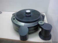
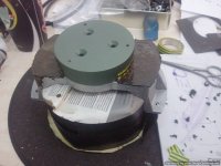
I couldn't resist the urge...
I just put one piece on top of the other to take a quick peak at how it
looks and disassembled the whole thing right away.
The varnish is still breathing and is ready to stick if pressure is applied.
This is an original color mix and I think it looks pretty good...
I 'll chew on my fingers for a week or so...
Attachments


Nah, you've ruined it now. Putting it together too early has just ruined the finish and you're customer just will not accept it, nope just ruined it.....
I guess the only thing now would be to start all over again.
Now what should you do with that totally ruined eyesore of a turntable..... Oh go on then I'll take it and see if I can salvage something out of it 🙂
I guess the only thing now would be to start all over again.
Now what should you do with that totally ruined eyesore of a turntable..... Oh go on then I'll take it and see if I can salvage something out of it 🙂
I couldn't resist the urge...
I just put one piece on top of the other to take a quick peak at how it
looks and disassembled the whole thing right away.
The varnish is still breathing and is ready to stick if pressure is applied.
This is an original color mix and I think it looks pretty good...
I 'll chew on my fingers for a week or so...
Yes. Understated and classy.
I'll be interested to see how you apply the various bits of text around the control buttons, and the model Id, etc.

I expect the factory would have used some sort of specialized silk-screen technique. Hopefully I can learn by your method. I've run into the need for lettering some of my projects as a final part of the process. And yet I don't have any of those necessary skills......so far.
-Steve
Nah, you've ruined it now.
Now what should you do with that totally ruined eyesore of a turntable..... Oh go on then I'll take it and see if I can salvage something out of it 🙂
You're joking, but my heart was pounding when doing this.
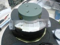
I was thinking about adding more "green" parts...ie the periphery ring, the record weight or the wider base part of the tonearm tower but i think i kept things to a good proportion.
Naah..i'm happy with the result.
Hello soundofvoid
This is very good work. I particularly like how the bevels on top of the legs match the angle of the bezel around the platter.
I've liked Denon turntables as long as I can remember!
Sincerely,
Ralf
This is very good work. I particularly like how the bevels on top of the legs match the angle of the bezel around the platter.
I've liked Denon turntables as long as I can remember!
Sincerely,
Ralf
I'll be interested to see how you apply the various bits of text around the control buttons, and the model Id, etc.
I expect the factory would have used some sort of specialized silk-screen technique.
-Steve
I was divided between engraving the letters and silk-screening them.
I took the top part to an engraver and he said it was a nightmare to do it
because it is circular AND sloped with a variable angle.
Then i thought about silk-screening on the rectangular buttons...but what
about the rest of them that are not rectangular?
So i have decided for silk screening on the original places but a bit different.
I will use standard unicode symbols for STOP , PLAY 33 and PLAY 45 ,
auto/variable and +/- on the buttons and instead of the company labeling, it's going to be a DP-1 DD by soundofvoid.
Just like the engravings on the faceplate of the PS/control box...and not in white but in a dark gray color...that i may use to paint the buttons too.
Another touch was to fill in the line just over the buttons and to produce
a single flat area painted in green.
I like it less cluttered.
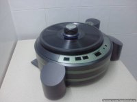
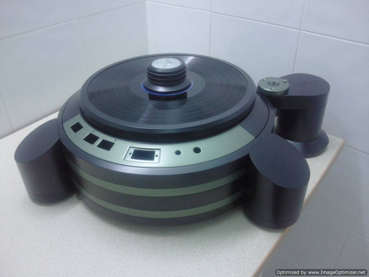
... I particularly like how the bevels on top of the legs match the angle of the bezel around the platter...Ralf
Thank you Ralf.
Design wise that is one of the main differences over my previous effort.
That and the fact that now the original DENON chassis is sinked in the top aluminium plate.
I have spent countless hours designing on the computer screen to make it more "one piece"
I particularly like the hiden spikes as the cups cover them from sight and make the foot look like one piece.
Side by side:
Attachments


You're joking, but my heart was pounding when doing this.
I was thinking about adding more "green" parts...ie the periphery ring, the record weight or the wider base part of the tonearm tower but i think i kept things to a good proportion.
Naah..i'm happy with the result.
🙂 I was joking. You should be happy with the result! it is a modern work of art, absolutely stunning and it's still to be finished. Please do not fall into that "I should add more" trap. I think you have it spot on, adding more colour here and there will only end in tears.
OK, maybe the top disk of the record weight......
My thoughts exactly.
It's very easy to get carried away and end up making it look garish.
I'll keep it as it is.
I'm very fond of the satin black...
It's very easy to get carried away and end up making it look garish.
I'll keep it as it is.
I'm very fond of the satin black...
Last edited:
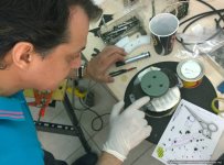
I have taken it to the silk-screener's for an assessment of the lettering and location of words.
It proves to be a very difficult item as it's round AND beveled.
He has asked from me to bring him another specimen that i didn't mind messing around with.
So i stripped another DP that is in a bad state (needs a respray badly) and brought him the top panel to help him with his work.
I'm waiting to hear from him...
I have taken it to the silk-screener's for an assessment of the lettering and location of words.
It proves to be a very difficult item as it's round AND beveled.
He has asked from me to bring him another specimen that i didn't mind messing around with.
So i stripped another DP that is in a bad state (needs a respray badly) and brought him the top panel to help him with his work.
I'm waiting to hear from him...
This brings up some idle thoughts I've had recently. It has come to my attention that it is possible to use a specialized inkjet printer to print text and designs on solid flat objects such as face plates for instruments. I think it was HW who mentioned that he uses inkjet printing to annotate the top facias on some of their record player models. But these are flat surfaces....
Yet, the technology seems to be there. Heck, we've been able to inkjet print directly onto CDR disks for some time.
So the next hurdle would be to inkjet print directly onto 3d solid objects similarly to how a cnc mill goes about carving the same objects. I'm guessing that if there aren't yet prototypes of such machinery, it won't be long before there are.
but just idle thinking.
re: silk screening onto curvy angled surfaces. The evidence suggests that it has been done on the original parts. Kinda' makes me want to learn Japanese so I can research further on Denon's (and others) older mfg methodology. * They were masters of their art.
-Steve
* as if I had time for such an endeavor.
I will wait to see what happens but i aim to use this battered specimen to make a CNC CAD program so that i can carve the letters into the metal.
In the next item...
In the next item...
Still waiting for the silkscreened part to arrive...
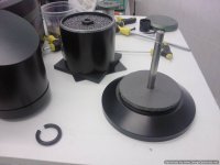
In the meantime i told myself that i had to do something (besides waiting and chewing my nails) and started with the tonearm tower.
It's basically a three part item and i had asked for free space between these parts so that i could compress between them energy absorbing layers.
So i have made myself a instrument to cut round flanges out of different materials and did my tests.
I have finally opted for a material used in sound proofing installations (a 1 mm lead sheet glued between two soft neoprene layers) and have cut two discs.
One was placed between the inox steel base and the leaded iron hollow part.
When fully loaded (with lead shot) the middle part, the 7mm soft layer compressed to 6mm and left 1 more mm to compress with the screw force...which was nice.
See some pics
Attachments

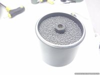
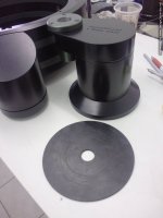
Then it was time to fill up the empty middle compartment with lead shot.
I used No 10 so that very little empty space was left.
After filling it up to 5mm from top i poured in thick truck gearbox oil to fill up any dead space between the lead shot.
It took some time (and a lot of stir) to see it top up.
Then it was time for the top "flange" out of the same material used in the bottom (protruding a bit...to compress later) and the top plate with the tonearm hole.
All screwed nicely tight.
Last part was a a donut shaped, medium hardness rubber pad to go under the tonearm tower...glued in place.
It all made a very dense and "dead" item (10 kgs).
All it's weight plus the rubber "sole" made it extremely stable...aka surefooted!
Some pics from the process:
Attachments
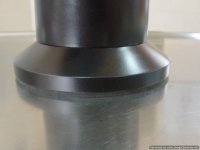


Next were the three feet.
I had to get a small funnel to drive in the hollow compartment the lead shot (this turntable is not very Rohs compliant, aint'it?) through an M8 screw hole and shake and add and shake and add it untill all of the compartment was filled.
Then it took ages to fill up the dead space with the same oil...about 3 hours for the first leg!
This is to show how thick it is and how slowly it settles...
So i used a big syringe with a small tube to drive the oil directly to the bottom
in the next ones and that made a lot of difference in time.
When i could see the oil top up i would screw the spike tight so that the o-ring would secure the chamber.
Then i made a cutout of the flange and cut it from sorbothane sheet.
I used 2mm thick while the free space for it was 1.5mm...so half a mm compression.
When it was in place the legs where screwed tightly and are not to be separated again from the chassis...
The whole idea as always is not just to make heavy parts but also try to incorporate various means of energy absorption and vibration damping.
I had a leg out of aluminium with inox steel and bronze parts, filled with half a kilo leadshot and thick gearbox oil that attached to the chassis with a flange of sorbothane.
I like it dead.
Like dead dead.
Attachments


It would be interesting to find out if your feet are absorbing more from the TT itself rather than from the outside.
The reason I say this is your use of such a thick oil around the lead almost turns it into a solid more than being able to scub off a wider range of resonances without it.
Depending on what you place it on, low low frequencys will still effect the stylus.
You need a counteracting movement of some kind to offset outside frequencys not easily done.
I prefer lead since it's hard to argue with on a overall basis.
A accelerometer or cheap MM cartridge and additional tonearm placed in a strategic place should capture what's working and not, but mass does solve more than most cheap junk on the TT market these days.
Looking good!
Regards
David
I hear you David!Thanks for watching an sharing ideas!
It is really something to watch thick oil mix with lead shot.
The final outcome is a mix that will take all the dead space,
will have no ringing (although lead is a "plastic" metal, the minute dimensions of the tiny lead spheres make each one of them very "live" and bouncy), will damp enormously the outward vibrations and filter heavily the inward ones.
Sorbothane transforms kinetic energy to heat and is there in layer form to "filter" as much of the vibrational energy climbing up the leg before it enters the chassis.
When i was doing my Mitsubishi project i had spent a day in a friends lab doing tests with accelerometers, different metals and various configurations of damping materials.
The outcome was that no single solution solves all the problems.
Using different materials that absorb energy AND mixing high mass metals solves most of them.
And of course i will advise the owner about where to place it and what to put underneath!
We are living in a great era.The materials are endless and all it takes is a little research and the will to put them to test!
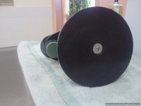
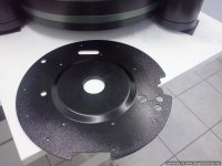
My work for the day...
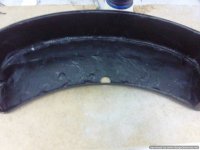
To cut and stick in place a 1.5mm thick layer of soft bitumine.
I placed the roll in the fridge to make it a bit harder and make cutting it easier.
Nasty sticky stuff!
I used it to cover the round metal part under the platter.
I suspect that it is there to cut any motor induced stray magnetic field from reaching the platter.
I weighted it before and after.It went from 450 to 550 grams.
Not bad and now not ringing at all!
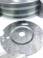
Then i did the same with the cover protecting the underside of the buttons cluster.
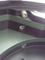
Last thing was to cut four sorbothane pcs that are going to be compressed between the new bronze thrust plate and the motor supporting U part.
The space is 3.5mm and the sorbothane is 4mm thick.
Just like i want it.
See pics:
To cut and stick in place a 1.5mm thick layer of soft bitumine.
I placed the roll in the fridge to make it a bit harder and make cutting it easier.
Nasty sticky stuff!
I used it to cover the round metal part under the platter.
I suspect that it is there to cut any motor induced stray magnetic field from reaching the platter.
I weighted it before and after.It went from 450 to 550 grams.
Not bad and now not ringing at all!
Then i did the same with the cover protecting the underside of the buttons cluster.
Last thing was to cut four sorbothane pcs that are going to be compressed between the new bronze thrust plate and the motor supporting U part.
The space is 3.5mm and the sorbothane is 4mm thick.
Just like i want it.
See pics:
Attachments

Ha...!
It seems there is a consensus on the subject...
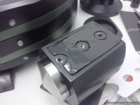
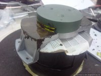
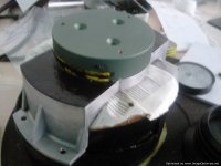
In the mean time i have painted the bronze thrust plate part with the same Nissan metallic green.
I thought: why not filling up with liquid bitumine the remaining compartments in the U part?
I wouldn't hurt anything...on the contrary it will help in damping the part more.
And so i did, but before took some precautions so it does not attach on the painted part.
Vinyl tape and a smear of oil would do the trick.
When it's dried i will remove the green part and paint the rest black (on the outside)...
It seems there is a consensus on the subject...
In the mean time i have painted the bronze thrust plate part with the same Nissan metallic green.
I thought: why not filling up with liquid bitumine the remaining compartments in the U part?
I wouldn't hurt anything...on the contrary it will help in damping the part more.
And so i did, but before took some precautions so it does not attach on the painted part.
Vinyl tape and a smear of oil would do the trick.
When it's dried i will remove the green part and paint the rest black (on the outside)...
Attachments
- Status
- Not open for further replies.
- Home
- Source & Line
- Analogue Source
- My new effort on making the ultimate DP-80