Goldie99 has kindly pointed out an error in the quoted values and part numbers for C2 and C3 in the Speaker Protection circuit of post #1796
The value should be 4.7uf, 63V and the Mouser part number I actually used when building my one is 710-860020772008C2 & C3 being shown as 47uf / 63V. The BOM 'value' shown is 47uF, but the Mouser part number is for a 4.7uF / 63V, albeit obsolete already.s

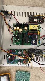
Got some time today and tested both the channels using a smps.
Readings channel 1 and 2
Supply : +/-39.5vdc (home voltage is usually high at my place)
Opamp pin4: -11.95vdc and -11.91vdc
Opamp pin6: -4.86vdc and -4.85vdc
R19/20 junction: 1mV and 1mV
Across R5: 0.556vdc and 0.567vdc
Readings channel 1 and 2
Supply : +/-39.5vdc (home voltage is usually high at my place)
Opamp pin4: -11.95vdc and -11.91vdc
Opamp pin6: -4.86vdc and -4.85vdc
R19/20 junction: 1mV and 1mV
Across R5: 0.556vdc and 0.567vdc
Attachments
@Mooly Forgive my ignorance here Karl, I'm about to place Mouser order this weekend for Geoff's boards, Will substituting R26 0.22R output resistor for 0.15R be very detrimental? I suppose the speakers only 'see' the last resistor.
I have a pair of unused Mills MRA 5W 0.15R non inductive resistors in the stash. For R23/24 I already have these in 0.22R. (thought they were Mills too)
I have a pair of unused Mills MRA 5W 0.15R non inductive resistors in the stash. For R23/24 I already have these in 0.22R. (thought they were Mills too)
Will substituting R26 0.22R output resistor for 0.15R be very detrimental?
I suspect it will make no difference to the operation in practice.
Powered up first amp board and I used a 0.1R/5w resistor in series with the positive supply and I set the bias to 0.01v. Input is shorted and offset is 0.00mV

Made the inductor using 16awg and 14 turns and put it off board and will be connected when all finished.

Made the inductor using 16awg and 14 turns and put it off board and will be connected when all finished.
The power dissipation should be equal in each FET as they are simply in series as far as current flow is concerned (assuming no load attached and no signal present). The current in R23 and R24 should be equal

There are no resistors in either supply rail. This is the original artwork from many many years ago and these are the only low value resistors in the amp.Or is it due to the 0.1 resistor with the positive supply?
I believe that the coil, to be truly effective, must be connected directly to the output of the mosfets, without interposing that piece of wire...
The wire has a small own inductance that adds to the coil's inductance, or it gets more complicated in this situation?
That'd rather apply to the Zobel network, the series connected capacitor C9 and resistor R25. You really want to avoid any stray inductance there.I believe that the coil, to be truly effective, must be connected directly to the output of the mosfets, without interposing that piece of wire...
More to the point - have you got the 10ohm 2W resistor in parallel with the inductor (it's there to damp the inductor impedance)?
A better way of powering an amp for a test is to use a lamp bulb in series with one of the AC power line wire. The bulb is a good detector in case of faults it will also detect if the amp will self oscillate.Powered up first amp board and I used a 0.1R/5w resistor in series with the positive supply and I set the bias to 0.01v. Input is shorted and offset is 0.00mV
View attachment 1348593
Made the inductor using 16awg and 14 turns and put it off board and will be connected when all finished.
Cheers!
Yes it’s on the amp board itself 10R/2W resistor.More to the point - have you got the 10ohm 2W resistor in parallel with the inductor (it's there to damp the inductor impedance)?
Yes it’s on the amp board itself 10R/2W resistorMore to the point - have you got the 10ohm 2W resistor in parallel with the inductor (it's there to damp the inductor impedance)?
Yes I know I always do it on my amp builds but as I am using a smps didn’t use it.A better way of powering an amp for a test is to use a lamp bulb in series with one of the AC power line wire. The bulb is a good detector in case of faults it will also detect if the amp will self oscillate.
If I'm not mistaken the resistor on the amp board is NOT in parallel with the off-board inductor. According to the circuit diagram and Prasi's layout, this is R26 and is shown as 0.22R 5W. See Mooly'post#1, the relevant part quoted below:Yes it’s on the amp board itself 10R/2W resistor.
1. The circuit diagram in this, post #1 is correct. The only omission is a 10 ohm 2 watt carbon/metal film across the output coil.
I'm not sure what Prasi's layout looks like tbh and whether the inductor was on the board or not but this shows the correct circuit configuration and with reference numbers to match the original hand drawn diagram in post #1

Attachments
- Home
- Amplifiers
- Solid State
- My MOSFET amplifier designed for music