Any idea about what value caps should be used for C+ and C- mentioned in the schematic and per the board layout on top of the mosfets? Also most of the MKP and FKP caps for 0.1uf/250v rated are bigger in size to fit on the board, any specific part numbers that fit easily without hindering the fuses?I cant remember if I posted them, here they are.
regards
Prasi
Thanks
C+ and C- can be anything that will fit.
5mm-7.5mm pitch. Up to 16mm diameter.
100uF would be the minimum value.
470uF common.
Anything you have on hand that fits the bill would be good.
If you are ordering parts anyway then perhaps something like this: Ultra long life, low impedance, good brand.
https://nz.mouser.com/ProductDetail/Chemi-Con/EKYB630ELL102ML25S?qs=IYueExuAvkqI5AG2KptHhQ==
I went with 1000uF on my build as I had 7.5mm/16mm caps on hand.

C12/C13 will fit a 5mm,7.5mm or 10mm pitch film cap.
https://nz.mouser.com/ProductDetail/WIMA/MKP4-.1-250-10P10?qs=q8ECNkb1/vMlS4csT09B1A==
Would be an optimum film cap.
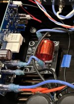
I didn't populate the 2x 5mm pitch film caps right beside the ground connection. I used one as a convenient place to run a wire to connect the Input ground to the PSU ground on that board. As seen by the blue wire.
5mm-7.5mm pitch. Up to 16mm diameter.
100uF would be the minimum value.
470uF common.
Anything you have on hand that fits the bill would be good.
If you are ordering parts anyway then perhaps something like this: Ultra long life, low impedance, good brand.
https://nz.mouser.com/ProductDetail/Chemi-Con/EKYB630ELL102ML25S?qs=IYueExuAvkqI5AG2KptHhQ==
I went with 1000uF on my build as I had 7.5mm/16mm caps on hand.
C12/C13 will fit a 5mm,7.5mm or 10mm pitch film cap.
https://nz.mouser.com/ProductDetail/WIMA/MKP4-.1-250-10P10?qs=q8ECNkb1/vMlS4csT09B1A==
Would be an optimum film cap.
I didn't populate the 2x 5mm pitch film caps right beside the ground connection. I used one as a convenient place to run a wire to connect the Input ground to the PSU ground on that board. As seen by the blue wire.

The coils are not critical at all but they must be air spaced (no magnetic former).
You can get a good idea from the ones I made hear:
https://www.diyaudio.com/community/threads/output-relays.191449/post-2660474
You can get a good idea from the ones I made hear:
https://www.diyaudio.com/community/threads/output-relays.191449/post-2660474
You can also just look up an inductor coil calculator online - mine came out to ca 15 turns, 30mm O/D, but I don't recall the wire gauge.
I used 18AWG wire for mine. I forget how many turns on a roughly 25mm former (plastic water pipe offcut). If I was winding again, I would go a gauge or two bigger just to give the coil a little more stiffness/solidity when wound.
Hi Manniraj,
I used 16ga wire.
https://www.diyaudio.com/community/threads/my-mosfet-amplifier-designed-for-music.119151/page-88
I used 16ga wire.
https://www.diyaudio.com/community/threads/my-mosfet-amplifier-designed-for-music.119151/page-88
Attachments
Thanks @Vunce I will get this wire https://www.amazon.com/dp/B07GBM6Y4Z?ref=ppx_yo2ov_dt_b_product_details&th=1. By the way did you use the original 1058/162 FETs or the Exicons in your build? Post #1731 and others confusing me where you mentioned to go with original FETs which I presume are 1058/162 but in other posts it was mentioned as Exicons ECW20xx 🙂
Last edited:
Let me know how many turns using 16awg as I have some 18awg wire left over from other builds.Hi Manniraj,
I used 16ga wire.
https://www.diyaudio.com/community/threads/my-mosfet-amplifier-designed-for-music.119151/page-88
There's plenty of online calculators for this.
For example: https://coil32.net/online-calculators/one-layer-coil-calculator.html
Using this tool, you get 18.225 turns around a 1" former with 16 AWG wire for an inductance of 6u. You can tinker with the diameter and wire dimensions to figure our what works for your scenario.
For example: https://coil32.net/online-calculators/one-layer-coil-calculator.html
Using this tool, you get 18.225 turns around a 1" former with 16 AWG wire for an inductance of 6u. You can tinker with the diameter and wire dimensions to figure our what works for your scenario.
I will also be using a +/-35vdc power supply to test this amp and do I need to consider changing any of the values? I am using the Prasi pcb board with all through hole parts and Exicon ECW10xxx series laterals. My build so farView attachment 1319741
I've finally lashed a power supply together. The only transformer I had in my spares box has two secondary windings at 25V/1A so provides an unregulated +/-38Vdc. So for now I'm only going to be able to do the dc measurements. On initial switch-on:
Thanks
Looking good so far. With the voltages you mentioned, you should be fine for initial dc/ac measurements prior to fitting the Exicons. As Mooly said in an earlier post, for lower power supply voltages than this, it may be necessary to reduce R27 to provide enough bias current for the 12V zener.
Following on from a query about the protection board I'm using, I thought it might be useful for anyone else working with Mooly's excellent amp so here is the protection stuff:


Its based on Doug Self's one in his Audio Power Amplifier Design book with MOSFETS in place of the original relay. Works great!
Its based on Doug Self's one in his Audio Power Amplifier Design book with MOSFETS in place of the original relay. Works great!
Attachments
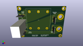
And on a similar topic as my previous post, here is all the data for an output board to match the Mooly Amp and contains the 6mH / 10Ohm elements of the Thiele network.
It's laid out so that it can be mounted either directly onto standard 3/4 inch pitch dual binding posts or stand-alone. It can also be mounted as either left or right hand pitch onto the binding posts (silk screened notation on both sides of the board).
It's laid out so that it can be mounted either directly onto standard 3/4 inch pitch dual binding posts or stand-alone. It can also be mounted as either left or right hand pitch onto the binding posts (silk screened notation on both sides of the board).
Attachments
Just to echo 'passive420's comment - my thanks @geoffw1 too.
I started a build of this amp a couple of years ago, got the pcb's made, built, & even checked the amps, but then got 'bogged down' in life.... this'll hopefully give me the kick up the proverbial to finish it...
I started a build of this amp a couple of years ago, got the pcb's made, built, & even checked the amps, but then got 'bogged down' in life.... this'll hopefully give me the kick up the proverbial to finish it...
- Home
- Amplifiers
- Solid State
- My MOSFET amplifier designed for music