Pin 4 🙂 pin 6 is the opamp output and should be around -6 volts.check for -12vdc at pin 6 of the opamp
Wish me luck boys and girls.
All going to plan, I should turn on the power tonight.
All going to plan, I should turn on the power tonight.
Last edited:
All ready to go!

Well, I can't find my 22R safety resistors and I don't have any fuses below 1A.
So no power up tonight.
I really need to get around to making a dim bulb tester for these occasions...
Without wiring up a different testing rig it will be quite difficult to get safety resistors in there anyway so I think I will run with small value fuses.
I will swing by the local retailer and grab some 100mA to 500mA fuses.
Tomorrow night is 'date night' so Saturday night will be testing night.

They really do save a lot of grief 👍I really need to get around to making a dim bulb tester for these occasions...
Problem these days is finding an incandescent bulb...I really need to get around to making a dim bulb tester for these occasions...
Apex recommendations is a 100Ohm/17 or 25W resistor in series with transformer primary side,if an incandescent bulb isn't available.
I whipped up a quick and dirty dim bulb tester:2. Confirm pin 7 of IC is connected to ground.
Confirm pin 4 is at -12 volts --- if you are using a low supply voltage you may need to drop R27 the 10 K feeding the zener to around 5K6 but only do this if the 12 Volts is low.
3. Confirm the output is at Zero volts to within a few millivolts.
4. Confirm that there is 0.6 to 0.7 volts across R5. This will show the current source Q2 and Q3 are working correctly.

A small jiffy box, a light fitting and a dual socket and voila!
Most suprisingly, the 100w bulb I found in my cupboard was made in New Zealand. Goodness knows how old that is. I don't imagine we have made bulbs in NZ for quite some time. We don't make much of anything anymore.
I also threw some 250mA fuses in place.
2) Pin 7 grounded
-11.9Vdc on Pin 4 on both left and right channels
3) 0.2mV left channel
0.6mV right channel
4) 0.594Vdc across R5 on both left and right.
Onwards to biasing.
I'm about to start on biasing.
Assuming I cannot get bang on 44mV drain to drain.
Am I better off being under or over?
Assuming I cannot get bang on 44mV drain to drain.
Am I better off being under or over?
I would like to torture my amps with square waves, difficult loads etc. To make sure it is stable.
However I would think that I need to attach my scope to the mosfet side of r26 to see if the amp is oscillating.
There isn't anywhere obvious to do this on the prasi layout.
I could attach a probe to the output spade terminal however this is on the wrong side of r26.
As I understand things, with a probe on the wrong side of r26. I could see no oscillation while the output stage is actually oscillating?
Assuming the above is correct. Should I just skip the stability testing and go straight to music?
If the amp is oscillating you would see it on the main output before the output coil and series 0.22 ohm.
Square wave testing is fine to do as long as you remember the 10 ohm Zobel resistor would need to be a high wattage type for sustained testing at high outputs and high frequency (in common with most designs intended for normal music reproduction). That can apply to testing with high amplitude high frequency sine as well.
Square wave testing is fine to do as long as you remember the 10 ohm Zobel resistor would need to be a high wattage type for sustained testing at high outputs and high frequency (in common with most designs intended for normal music reproduction). That can apply to testing with high amplitude high frequency sine as well.
My thoughts exactly.the amp is oscillating you would see it on the main output before the output coil and series 0.22 ohm
I can't see anywhere to attach a probe that would be before the output networks so I guess I will just skip this step.
We know this design is very stable anyway.
G'day Guys,
Another member has requested the gerbers to my board with the thiel network and relay so here goes:
2 Versions.
The first is an improved version of the one I have used in my build with an extra 7mm for the inductor length as space was a bit tight on mine.
This one uses Amplimo relays or anything of the same footprint.

The second version uses an Omron G2R series relay.

This version has additional connections for the ground as this is a SPDT type meaning the output can be shorted to ground when the amplifier output is disconnected from the speaker. Also the extra inductor length compared to the boards I used in my amp.
This version is untested, however I have used the basic design minus the inductor in some recent builds.
653-G2R-1-E-DC12 from mouser is very well stocked.
I believe the amplimo relay is better as it is designed specifically for speaker protection. However they are harder to find and more expensive.
I purchased mine from:
https://www.toroidal-transformer.com/shop/high-end-audio/loudspeaker-relay.html
Another member has requested the gerbers to my board with the thiel network and relay so here goes:
2 Versions.
The first is an improved version of the one I have used in my build with an extra 7mm for the inductor length as space was a bit tight on mine.
This one uses Amplimo relays or anything of the same footprint.
The second version uses an Omron G2R series relay.
This version has additional connections for the ground as this is a SPDT type meaning the output can be shorted to ground when the amplifier output is disconnected from the speaker. Also the extra inductor length compared to the boards I used in my amp.
This version is untested, however I have used the basic design minus the inductor in some recent builds.
653-G2R-1-E-DC12 from mouser is very well stocked.
I believe the amplimo relay is better as it is designed specifically for speaker protection. However they are harder to find and more expensive.
I purchased mine from:
https://www.toroidal-transformer.com/shop/high-end-audio/loudspeaker-relay.html
Attachments
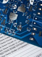
Mooly slim SMD version now built (minus MOSFETS as yet).

I've found one error with my KiCad footprint for T1,T2,T3 and T7 (ZXTP5401ZTA) meaning the actual footprint is smaller than the physical device. There's room for the devices to fit in place but the pads are closer together than the device pins. I've managed to solder them in place but they're not ideal by any means.
![IMG_20240604_142903696[1].jpg](https://www.diyaudio.com/community/data/attachments/1225/1225988-60aee043b91da0d4d293639ff8e4a611.jpg?hash=YK7gQ7kdoN "IMG_20240604_142903696[1].jpg")
Next step is find a suitable power supply amongst my bits and pieces so I can do some dc tests.
I've found one error with my KiCad footprint for T1,T2,T3 and T7 (ZXTP5401ZTA) meaning the actual footprint is smaller than the physical device. There's room for the devices to fit in place but the pads are closer together than the device pins. I've managed to solder them in place but they're not ideal by any means.
Next step is find a suitable power supply amongst my bits and pieces so I can do some dc tests.
Hi Geoff,
Did you get the ZXTP5401 in SOT-223-4 by mistake? This package size is slightly bigger than SOT-89-3.
Both NPN/PNP on the BOM are in SOT-89-3 which fit perfect.
SOT-89-3 ZXTP5401Z.pdf
SOT-223-4 ZXTP5401G.pdf
Did you get the ZXTP5401 in SOT-223-4 by mistake? This package size is slightly bigger than SOT-89-3.
Both NPN/PNP on the BOM are in SOT-89-3 which fit perfect.
SOT-89-3 ZXTP5401Z.pdf
SOT-223-4 ZXTP5401G.pdf
Attachments
Last edited:
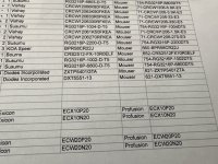
Found the error!
The BOM lists ZXTP5401GTA in the ‘Part Number’ column. That’s an SOT-223-4 package.
The ‘Supplier Part Number’ column lists the correct ZXTP5401ZTA package size.
So, the board pads are good, but you were unlucky to look at the wrong column.🙁
The BOM lists ZXTP5401GTA in the ‘Part Number’ column. That’s an SOT-223-4 package.
The ‘Supplier Part Number’ column lists the correct ZXTP5401ZTA package size.
So, the board pads are good, but you were unlucky to look at the wrong column.🙁
Attachments
Last edited:
Definitely my goof on ordering the parts!😡 On the other hand, it will give the opportunity to measure the temperatures of the highest dissipation devices T3 and T5 with the two different package sizes. Looking on Mouser, 5551 and 5401 devices are actually available in either package size and if necessary, the board can be rejigged for the larger package . Might be worth doing anyway. Lets see what the dc tests show 🙂
- Home
- Amplifiers
- Solid State
- My MOSFET amplifier designed for music