@rephil would you mind posting a few clear pictures of your build? I'm curious because I never could get my pair working without some sort of oscillation. Tried a lot of things, from different caps to ground loop breaker to changing the wiring a couple different ways without a long term solution. Specifically I am now wondering what type of capacitor you used for C7 (22pf) and possibly for C8 (0.1uf). I changed C8 from a WIMA Polypropylene to a Panasonic Polyester with no change, but I never changed C7 (currently a Kemet Ceramic MLCC). I disassembled the amp from frustration, but found the boards after moving a few months ago and would like to try again to see if I can get it working properly.
Hi rephil, congratulations!
I'm so glad that you have another nice DIY amplifier!
I feel for you.
Have plenty of music hours and good wine.
I'm so glad that you have another nice DIY amplifier!
I feel for you.
Have plenty of music hours and good wine.
Thank you for all the kind words, what can I possibly add to what you have said 🙂You did reach the perfection there Mooly with this nice power amp !
I already did that for you a little while ago 😉I could drink some glass of wine
The topology of the amp is such that it should be very stable and forgiving under pretty much any build conditions, even down to building it on a breadboard. I used a tubular polystyrene for the 22pF and common film caps for anything like 0.1uF.would you mind posting a few clear pictures of your build? I'm curious because I never could get my pair working without some sort of oscillation. Tried a lot of things, from different caps to ground loop breaker to changing the wiring a couple different ways without a long term solution.
The only 'mission critical' part in the whole amp beside ensuring you have genuine lateral fet's fitted is the TL071.
I'm forgetting @prasi in all this. 👍 those boards were great.Many thanks also @prasi for the so good PCB that he provided to all of us. It was easy to work, it is very well done and provides good sounds without any problem.
I have a couple of boards, PM meAnybody selling 2 boards to USA? Thx
@rephil would you mind posting a few clear pictures of your build? I'm curious because I never could get my pair working without some sort of oscillation. Tried a lot of things, from different caps to ground loop breaker to changing the wiring a couple different ways without a long term solution. Specifically I am now wondering what type of capacitor you used for C7 (22pf) and possibly for C8 (0.1uf). I changed C8 from a WIMA Polypropylene to a Panasonic Polyester with no change, but I never changed C7 (currently a Kemet Ceramic MLCC). I disassembled the amp from frustration, but found the boards after moving a few months ago and would like to try again to see if I can get it working properly.
Hi bullitstang
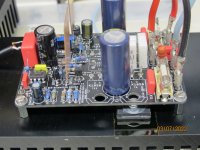
I did put a 22pF tubular polystyrene, 160Vv for C7. The C8 is a Wima 0.1uF 63V, as can be seen on the jpg. There is nothing strange here. All what I did is to follow any information I did find from Mooly. I have measured every component choosing the same values for each component in each channel. So I did get the same performing channels. That's OK. You can see the black wire under the PCB connected from the I/P connected to the GND from the power supply on the PCB. It is a 1.5mm² wire, and I did check that it was not badly connected as the PCB is not very distant from the heatsink.
I did also perform all good solders : at first I did scratch every wire of each component with a cutter in order to get good electrical contact from the wire with the solder.
I did measure some transistors, well all except the Mosfet. I did put the highest valued hFE on my circuit evaluating the HFe and the Vbe (I found the best at around 200 hFE at 10mA and at 5mA at this 5mA it is on a DCA75). I did check and checked again in order to be sure of what I did get. There is a procedure in order to compare the same transistors at the same temperature at the same day. The DCA is fast, my procedure a not so fast. DON'T TOUCH the transistors with your warm fingers ! Put the transistors you will measure on a big piece of aluminium and above it another piece of aluminium in order to get the mostly same temperature for all of them. Measure the faster you can, write the value
you find, let them cool some hours, then redo the measurements on those who look the same values ... It is a painful procedure, as I am knowing there is not any faster procedure for the diy job.
In the attached you find what you did ask to see from me and I did put a bit more.
Please, understand that I did my best to respect what did write to us Mr Mooly. The input capacitor is a 150pF polycarbonate I had around. Both the 1000uF placed at the output on the PCB are there because I had that home, and there is no other reason for this. All my components are genuine ones, the 2N5551 and the 2N5401 come from Profusion PLC as it is for the Mosfet ECW20N20and the ECW20P20. Bought long before the Brexit ...
For the time now, I am hearing some Cantata from J.S. Bach, and it is wonderful to be heard ... A very big thank you to Mooly for a cheap power amp that is so good sounding !
Have too the pleasure to get Mooly's power amp good working, and be satisfied like I am.
Best regards
rephil
Attachments
-
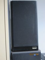 one Pioneer Prologue 70.JPG363.2 KB · Views: 270
 -
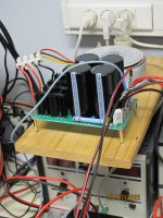 power supply.JPG388.8 KB · Views: 257
 -
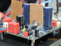 C8 and the wire under the PCB connected to the GND.JPG398.2 KB · Views: 261
 -
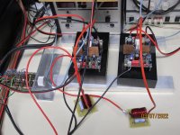 both channel and the variable input resistor.JPG467.8 KB · Views: 289
 -
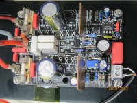 one channel.JPG429 KB · Views: 301
 -
 one channel side view.JPG408.7 KB · Views: 292

Thanks for the detailed pictures - I have a current project I'm finishing, but looking forward to getting mine singing as good as yours. Let's hope they only need a little fine-tuning.
Nice pictures and very detailed presentation!
You have done a very good job my friend.
Good luck with your next project.😉
You have done a very good job my friend.
Good luck with your next project.😉
Nice pictures and very detailed presentation!
You have done a very good job my friend.
Good luck with your next project.😉
Hi Thimios
Thank you for these kind words. I have to put all that nice power amp in a nice chassis. It takes time to do that, and I am very slow !
My nice next project will have some delay to be done my friend ! It is yes the next one on the list, and I would like to already be at work on it, but I want to finish this one including putting it in a chassis ! It is diyaudio my friend, and each project is never the last one ... But I don't know if this next project could be a better sounding amp as is this one. Mooly did a great job you know, and it is a cheap power amp. Who is the guy that did say that expensive power amps sound better as cheap ones ?
Have a nice day Thimios.
Best regards
rephil
Yes i know my friend.Hi Thimios
Thank you for these kind words. I have to put all that nice power amp in a nice chassis. It takes time to do that, and I am very slow !
My nice next project will have some delay to be done my friend ! It is yes the next one on the list, and I would like to already be at work on it, but I want to finish this one including putting it in a chassis ! It is diyaudio my friend, and each project is never the last one ... But I don't know if this next project could be a better sounding amp as is this one. Mooly did a great job you know, and it is a cheap power amp. Who is the guy that did say that expensive power amps sound better as cheap ones ?
Have a nice day Thimios.
Best regards
rephil
Take your time and enjoy the Music!
No, I don't think an expensive amp necessarily sounds better than a cheap one but you will never know anything about this beffore you will try the next.
Bad thing for our pockets ...ha ha ha
That's why i have so many tested but not housed amplifiers.😭
May be i will try this amplifier but after The PASS F4 and USSA5.
Unfortunately long time in my list...😡
I can't be fast because of money
Stay Safe my friend!
thimios
Last edited:
Hi Mooly
I did check my speaker delay circuit, it cannot be longer as 2-3 seconds. But having inserted it in the system, I have no more a big thump at power on, not even a very tiny sound that remember a thump at power on. I don't know if it could be better to have a delay of 6 seconds ?
I see that the output, the resistor 0.22Ohm 5W becomes very warm. It makes me nervous as it is not good for the PCB. I can't put my finger on it for more than around one second. Maybe it could be better to put two 0.47Ohm 5W in parallel or two 0.1Ohm in series instead of only one 0.22Ohm 5W. As is the PCB now, I could dissolder the 0.22Ohm an put 0.1Ohm 5W at the place, and before the coil, I could put in series with it the other 0.1Ohm 5Watt. So the dissipated power would be halved on the PCB. The 0.22Ohm 5Watt connected at each power transistor are not very warm, they are both OK.
Please Mooly, what is your opinion ?
I would be happy to get the PCB modded by the good Prasi that do so nice PCBs, putting only one transistor connected at each rail, as one can choose to put the ECW20(N or P)20 when more current is wanted instead of placing the ECX10(N or P)20. So more place would be available for the 0.22Ohm 5W (for better dissipating the warmth developped at each rail).
As I like to make my own PCBs by myself (diyaudio), it would be kind from Prasi to get the PDFs with the tracks on the copper side not reversed (the text on the copper side should be reversed) and the silk screen reversed. I print the copper side on some paper and then I put the tracks on the copper warming the paper contacting the copper at around 150° C, for around 90sec. I get very nice PCBs, good as those that our friend Thimios produces with another procedure ... It is also possible to get two sided PCBs this way (I made so some small two sided PCBs), it is a question of registrating the two sides ... I ask this help because it is above my skills to produce so nice and so good PCBs as Prasi does. He is a skilled Master ...
Best regards
rephil
Thanks 🙂 Simple designs can often work out best for sonics but I'll be the first to admit that this one sounds far far better than the sum of its parts would ever suggest.But I don't know if this next project could be a better sounding amp as is this one. Mooly did a great job you know, and it is a cheap power amp.
Hi rephil,isn't your pcb by Prasi?Hi Mooly
I did check my speaker delay circuit, it cannot be longer as 2-3 seconds. But having inserted it in the system, I have no more a big thump at power on, not even a very tiny sound that remember a thump at power on. I don't know if it could be better to have a delay of 6 seconds ?
I see that the output, the resistor 0.22Ohm 5W becomes very warm. It makes me nervous as it is not good for the PCB. I can't put my finger on it for more than around one second. Maybe it could be better to put two 0.47Ohm 5W in parallel or two 0.1Ohm in series instead of only one 0.22Ohm 5W. As is the PCB now, I could dissolder the 0.22Ohm an put 0.1Ohm 5W at the place, and before the coil, I could put in series with it the other 0.1Ohm 5Watt. So the dissipated power would be halved on the PCB. The 0.22Ohm 5Watt connected at each power transistor are not very warm, they are both OK.
Please Mooly, what is your opinion ?
I would be happy to get the PCB modded by the good Prasi that do so nice PCBs, putting only one transistor connected at each rail, as one can choose to put the ECW20(N or P)20 when more current is wanted instead of placing the ECX10(N or P)20. So more place would be available for the 0.22Ohm 5W (for better dissipating the warmth developped at each rail).
As I like to make my own PCBs by myself (diyaudio), it would be kind from Prasi to get the PDFs with the tracks on the copper side not reversed (the text on the copper side should be reversed) and the silk screen reversed. I print the copper side on some paper and then I put the tracks on the copper warming the paper contacting the copper at around 150° C, for around 90sec. I get very nice PCBs, good as those that our friend Thimios produces with another procedure ... It is also possible to get two sided PCBs this way (I made so some small two sided PCBs), it is a question of registrating the two sides ... I ask this help because it is above my skills to produce so nice and so good PCBs as Prasi does. He is a skilled Master ...
Best regards
rephil
Why you ask about Prasi pcb pdf?
''I see that the output, the resistor 0.22Ohm 5W becomes very warm''
Is it worm even if input signal is absent?
PS .I understand now,you ask about a pcb version that will fit only one pair of out fets.
Last edited:
I see that the output, the resistor 0.22Ohm 5W becomes very warm. It makes me nervous as it is not good for the PCB. I can't put my finger on it for more than around one second. Maybe it could be better to put two 0.47Ohm 5W in parallel or two 0.1Ohm in series instead of only one 0.22Ohm 5W. As is the PCB now, I could dissolder the 0.22Ohm an put 0.1Ohm 5W at the place, and before the coil, I could put in series with it the other 0.1Ohm 5Watt. So the dissipated power would be halved on the PCB. The 0.22Ohm 5Watt connected at each power transistor are not very warm, they are both OK.
Sorry, I missed that bit.
The series 0.22 ohm should run totally cold with no signal and barely warm even at loud levels.
The resistor being hot doesn't make sense 🙂 because I think you mentioned that the DC offset is only a fraction of a millivolt (so no DC flowing in the load) and that there is no sign of instability on the scope.
I would check all those again when the resistor is hot. Check the DC offset is zero. Measure the DC voltage across the 0.22 ohm. Check with the scope to make sure no HF oscillation is present. Measure on both sides of the resistor.
Is the Zobel network correctly fitted (the 10 ohm and series 0.1uF) from output to ground?
Hi Mooly
Thank you for your answer.
I am sorry to report that I did not verify at the time of writing how much the resistors were warm. They are really not very warm at all, it is my memory that remembered that when I had problems with the 10Ohm 3W in the Zobel (it did burn). At the time I did find the output resistor hot. After hours (today) hearing good music with pleasure, this without interruption at good level, obviously not the level that is used in a party, only what is needed to well enjoy music, I can and I did put my finger on the output resistor letting it all the time I wanted in contatct, this without any problem.
Thus Mooly, I beg your pardon for speaking of an already solved problem I have had (as you did say, probably some wire badly connected). I had to check before I wrote ... I am very sorry to report what is not the reality. Sorry to have disturbed you for nothing Mooly ! The power amp has no problem.
Best regards
rephil
👍 no problem.
Enjoy 🙂
Hi Mooly
Thank you for your understanding ! You know, I have been very chocked by the resistor that did burn ! I did look in the circuit and did only see that the output 0.22Ohm 5Watt resistor was hot ! So it remains in my mind this problem, and it came back at a bad moment ! It was in absolute the first time I have had such a problem in one circuit I build. There is always a first time ...
I am for now hearing the Belkis Queen of Sheba from Respighi. A Chandos CD. Wonderful sound produced by your outstanding power amp ... designed for music. Yes it is the truth, it is for hearing the best music in your (and now mine) home. Such a quality ! Thank you Mooly.
Best regards
rephil
- Home
- Amplifiers
- Solid State
- My MOSFET amplifier designed for music