Just a quick draw in ltspice. Notation is not the same, but you should get the idea.
Also I have changed gate stoppers on 2SK1058 to 330ohm, because input capacitance on N channel mosfet is lower than P channel.
Gate stoppers together with mosfet parasitic capacitances act like a LPF. You need symmetry in order to achieve same positive and negative slew rate.
Hope this helps for a better amplifier.
Regards,
Tibi
Attachments
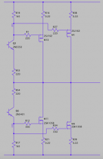
Excuse for my drawing mistake on Q6. In my drawing, Q6 should be horizontally mirrored.
Regards,
Tibi
Regards,
Tibi
Hi Goldie99 🙂
Please, let me know when the PCBs will come back to you as we are april 06 and the belgian post should bring them back to you today.
I am so sorry that brexit did part Europe again. We should take care to get better politicians in every country !
Have a nice day Alan.
Best regards
rephil
Please, let me know when the PCBs will come back to you as we are april 06 and the belgian post should bring them back to you today.
I am so sorry that brexit did part Europe again. We should take care to get better politicians in every country !
Have a nice day Alan.
Best regards
rephil
Hi Scchillg11
Your two nice black PCBs did arrive today to me in perfect conditions. Thank you so much for your friendly help.
Have a very nice end of this day Günni ! Now I will take the time to build well this nice amp done for music ... Thank you for this gift Mooly 🙂!
Best regards
rephil
Your two nice black PCBs did arrive today to me in perfect conditions. Thank you so much for your friendly help.
Have a very nice end of this day Günni ! Now I will take the time to build well this nice amp done for music ... Thank you for this gift Mooly 🙂!
Best regards
rephil
Hi Mooly
I am trying to get all the components needed for the build. So I have a question (well they are two) :
The needed 2SJ162 and 2SK1058 are very difficult to be found, those genuine I mean.
I have found in my drawers some (a very small quantity of) Exicon Lateral Mosfet I did buy years ago at Profusion Plc, some you are saying are OK for the build.
As I would like to put only two power transistors on each PCB and not 4 as it is possible here is the first question : please what should I select from those : the ECX10N20, ECX 10P20 or the ECW20N20 ECW20P20 ?
It seems that the ECW20 (N or P) 20 are able to give 16 A. Are they suitable and if yes are they values that should be changed in the PCBs ?
What I want to get is an amplifier aimed at providing good classical music, that is the only use planned for them.
I have one old (NOS mine) toroidal transformer 30Vac-0-30Vac, 500VA that should provide a good power supply. It was done at the time where 220Vac was the standard value of the main where I lived. Now it is 230Vac ...I suppose it will deliver around 44Vdc and not the expected around 42Vdc. Is that a problem ?
Thank you for your answer Mooly.
Have a nice day !
Best regards
rephil
The Exicon devices should be fine and have been used by others as far as I know. The 16A parts are referred to as a 'double die' device meaning two 8A devices in parallel in the same package. Again others have used these without issue and I would not foresee any problems. No changes are needed with the amp other than that ideally the quiescent bias should be doubled to around 200 milliamp but I doubt you will hear any difference if you run lower than that for cool running.
The transformer question really depends on 'how good it is'. If used with a higher input voltage than its maximum official design capacity and if the core is marginal in terms of magnetic material (in other words its 'lightweight' and been made down to a price with no margins built in) then the higher voltage may push the core toward magnetic saturation more readily. I suspect it will be fine though 🙂
The transformer question really depends on 'how good it is'. If used with a higher input voltage than its maximum official design capacity and if the core is marginal in terms of magnetic material (in other words its 'lightweight' and been made down to a price with no margins built in) then the higher voltage may push the core toward magnetic saturation more readily. I suspect it will be fine though 🙂
several PA amplifiers use j162 and k1058, they can be found for cheap on the second-hand market (C-Audio amp among others)
Last edited:
Hi Mooly
Thank you for your answer. I will use the Exicon ECW20(N or P)20. It is my first Mosfet amplifier, so I have yet no experience in building one such amplifier. I will check the quiescent current and see what is needed for good music, maybe measuring the THD at 1kHz.
The transformer I have here new is a Talema toroidal one and I did get it many years ago from RSComponents. For health problems with my wife that I have lost in 2001 after a long illness, and then my son that has been very, very ill after her death, I have had some years I did not proceed with what I was planning to do at the time. The classical problems that people encounter in their life sooner or later as you already know !
I hope for the best with your fine amplifier designed for music. Again many thanks for your friendly help.
Best regards
rephil
@huggygood : thank you for this information, but I have already home the transistors, the transformer and many other components needed. So I prefer to use what I have here : in my opinion, it is cheaper not to buy what you have already home. I am sure that you agree with me. This kind of informations are always very precious as they can safe the project you are considering, thank you !
Best regards
rephil

Hi Mooly
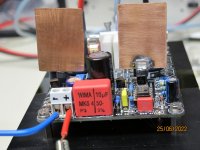
I have mostly finished to populate the two PCBs just now.
I have measured a very low offset for the board yet without power transistors, and I did not finished to solder the power transistors on this PCB. On the second PCB, with the power transistors soldered (one ECW20P20 and one ECW20N20), the offset is around 1.9mV. It is not below 1mV, but this kind of offset seems good to me. Mooly, please what is your opinion about this offset ?
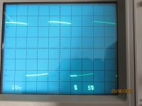
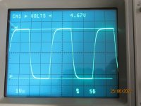
I did put the bias at around 60mV between the two 0.22Ohm, that should be 0.06/0.44 = 136mA. I did not attach neither a load at the output for the moment nor the 6uH having the 10Ohm in //. It will be done when the temperature in my lab will be lower as the sun is here for the time. So, for today I did look at the sine, triangular, and rectangular waves on the scope. At 1kHz, the rectangular shape is really perfect, with no overshoot at all. At 50kHz, the rectangular shows the shape to be no more so beautiful, but the input filter is there to work against what is nice to see on a scope as expected : the high frequencies abegin to be filtered ...
This is my first measurements, and the amp look to work mostly as I hoped.
Thank you for this nice amplifier you designed for music : I expect much from it, and it seems to promise even more to me !
Have a nice day Mooly.
Best regards
rephil
I have mostly finished to populate the two PCBs just now.
I have measured a very low offset for the board yet without power transistors, and I did not finished to solder the power transistors on this PCB. On the second PCB, with the power transistors soldered (one ECW20P20 and one ECW20N20), the offset is around 1.9mV. It is not below 1mV, but this kind of offset seems good to me. Mooly, please what is your opinion about this offset ?
I did put the bias at around 60mV between the two 0.22Ohm, that should be 0.06/0.44 = 136mA. I did not attach neither a load at the output for the moment nor the 6uH having the 10Ohm in //. It will be done when the temperature in my lab will be lower as the sun is here for the time. So, for today I did look at the sine, triangular, and rectangular waves on the scope. At 1kHz, the rectangular shape is really perfect, with no overshoot at all. At 50kHz, the rectangular shows the shape to be no more so beautiful, but the input filter is there to work against what is nice to see on a scope as expected : the high frequencies abegin to be filtered ...
This is my first measurements, and the amp look to work mostly as I hoped.
Thank you for this nice amplifier you designed for music : I expect much from it, and it seems to promise even more to me !
Have a nice day Mooly.
Best regards
rephil
I'm pleased it all seems to be going well. The 1.9mv offset is fine and is determined by the particular TL071 opamp used. All good 🙂
Real measurement and simulation should agree very closely for this amp. This is is at 50kHz and -/+30 volts output swing. I would not recommend you try that amplitude though because at that frequency the Zobel network would be very highly stressed (as it would in any amp).

Real measurement and simulation should agree very closely for this amp. This is is at 50kHz and -/+30 volts output swing. I would not recommend you try that amplitude though because at that frequency the Zobel network would be very highly stressed (as it would in any amp).
I'm pleased it all seems to be going well. The 1.9mv offset is fine and is determined by the particular TL071 opamp used. All good 🙂
Real measurement and simulation should agree very closely for this amp. This is is at 50kHz and -/+30 volts output swing. I would not recommend you try that amplitude though because at that frequency the Zobel network would be very highly stressed (as it would in any amp).
View attachment 1066040
Hi Mooly
I did not try such a high amplitude, I did use the minimum amplitude that my frequency generator allows, that is 50mVPP at the input as the gain of the power amp is high. I did add a few home made heatsink to the Vas transistors T3 and T5 that people say they become 'so' warm. If all goes well, I will explain the way to produce them, so nobody will say that these transistors are to warm. When I did produce them for the TO92 transistors, I did produce the heatsink (and tested) in order to dissipate 360mW in the TO92, and what I have got is some warmth (max around 40°C, measured, having 22°C in my lab), it means that dissipating 360mW in the TO92 you are able to maintain your fingers on the transistor without any problem.
In the power amp, these transistors are even not warm at all using these heatsink, so it should be good. I don't live in Afrika and obviously I don't expect a tremendous rise of temperature home.
Thank you for your reply Mooly. I will check the TL071 from TI, these are a bit old : more than 30 years old.
Best regards
rephil
The opamp will be fine, the offset you are getting is just the DC input offset of the opamp and it is well within spec.

The VAS transistor and the current source transistor will run hot but the dissipation is well within limits for the specified transistors running on no more than -/+45 volt rails. T092 clip on heatsinks used to be reasonably common many many years ago but have become a rarity these days.
Oh wow, Farnell do some. HOW MUCH 😱
Hi Mooly,The opamp will be fine, the offset you are getting is just the DC input offset of the opamp and it is well within spec.
View attachment 1066060
The VAS transistor and the current source transistor will run hot but the dissipation is well within limits for the specified transistors running on no more than -/+45 volt rails. T092 clip on heatsinks used to be reasonably common many many years ago but have become a rarity these days.
Oh wow, Farnell do some. HOW MUCH 😱
View attachment 1066063
Thank you for your answer. In fact you are a good doctor, and I could get the around 1.9mV now at around 0.25mV only changing the TL071CP with a TL071ACP. It is the input offset voltage that was concerned.
I have got a problem with the output 10Ohm 3W (in the Zoble) that I had : it burned at once when I did put the amp on. There is no explanation for me, as there was not any oscillation to be seen on the scope. A bad 10Ohm 3W ? A fake ? After putting another 10Ohm 5W in the Zoble, all went OK, no damage at all else than the 10Ohm 3W.
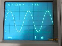
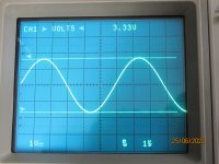
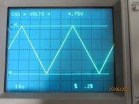
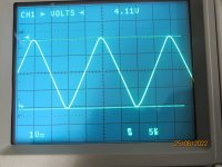
Today, I will try to put some pictures of what I see on the scope : the rectangular shape at 50Hz, at 1kHz, at 50kHz. The sine shape at 1kHz, 50kHz, 170kHz it is the bandwith of the amp on my bench, the triangular shape at 1kHz, 50kHz.
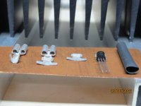
I will provide the photography of the heatsink mounted on the Vas transistors and how I did get that done. It costed mostly nothing. But it is a bit fast, as the amp has to be used a lot before I can say it is good.
What I did use is to be seen on the photography. Th copper is 0.5mm x 25mmx 35mm. I did use the copper that people use on the roof ... I don't remeber how many years I have had it home, they are to many.
I did use a flat connector sleeve not isolated, 6.35mm, Reichelt sell it at 0.06€ each including VAT.
I did use (not really necessary) at the end of the build a heat shrink tubing SDH 4.8 SW (around 5mm diameter), shrink ratio 2:1. It cost at Reichelt 0.41€ including VAT for 10 x1m.
Maybe it can cost less on eBay, I don't know.
It is difficult to solder the assembly on the PCB, there is very little place to do it, and your finger should not be used ... but you have to do that.
Some other pictures to be downloaded now.
Best regards
rephil
Attachments


I have got a problem with the output 10Ohm 3W (in the Zoble) that I had : it burned at once when I did put the amp on. There is no explanation for me, as there was not any oscillation to be seen on the scope. A bad 10Ohm 3W ? A fake ? After putting another 10Ohm 5W in the Zoble, all went OK, no damage at all else than the 10Ohm 3W.
I have no explanation for that at all tbh. The resistor is AC coupled via a 0.1uF cap and so only very high amplitude high frequency oscillation could make it burn. Something like having an input ground floating might do something like that. Can't think of anything else really.
Hi Mooly
I can't delete the last sine at 50kHz that is twice in the attached files. Sorry.
I have found how to do it, but a bit late ...
Yes this amp you did for music promise very much, I hope to get it. Thank you Mooly.
have a nice end of this day !
Best regards
rephil
I can't delete the last sine at 50kHz that is twice in the attached files. Sorry.
I have found how to do it, but a bit late ...
Yes this amp you did for music promise very much, I hope to get it. Thank you Mooly.
have a nice end of this day !
Best regards
rephil
Attachments
I have no explanation for that at all tbh. The resistor is AC coupled via a 0.1uF cap and so only very high amplitude high frequency oscillation could make it burn. Something like having an input ground floating might do something like that. Can't think of anything else really.
Hi Mooly
It is very possible : there are many floating wires c onnected to the amp. It might be exactly that. All is OK now, and the 10Ohm 3W in the Zobel was the only damaged thing here. But what a smell !
Those kind of fumes are renot a good thing.
""I have got a problem with the output 10Ohm 3W (in the Zoble) that I had : it burned at once when I did put the amp on. There is no explanation for me, as there was not any oscillation to be seen on the scope. A bad 10Ohm 3W ? A fake ? After putting another 10Ohm 5W in the Zoble, all went OK, no damage at all else than the 10Ohm 3W.""
Hi rephil,i can imagine only one reason for this.
Amplifier oscillates at very high frequency.
What is the input condition in this case?
Open,shorted,connected at generator?
Is the input gnd loosen?
Hi rephil,i can imagine only one reason for this.
Amplifier oscillates at very high frequency.
What is the input condition in this case?
Open,shorted,connected at generator?
Is the input gnd loosen?
- Home
- Amplifiers
- Solid State
- My MOSFET amplifier designed for music