the dissipation in the reduced track length is irrelevant.Yes... isn't that what I'm saying.
The trimmer will be set to say 220 ohm. The wiper will always see 6ma flowing as that is a constant (and that value is well within the 32ma limit) and so the dissipation over the part of the resistive track that's in use will be 7.9 milliwatts.
It's the current that has become the limitation.
Let's go the other way.
We have a 500mW 500r 32mA pot.
Let's reduce the resistance to 5r (1% of the maximum)
Now increase the current until the dissipation is 50mW (only 10% of the maximum).
The current would be 100mA
What's the problem? the dissipation is way below the maximum.
The "problem" is that the current is the limiting factor. It must never exceed 32mA and preferably be less than our chosen long term value of 22mA, or 16mA, or 10mA
These give maximum dissipations when turned to max resistance of 242mW (~50%), or 128mW (~25%), or 50mW (~10%).
But we have set our CURRENT limit to our preferred maximum. The ACTUAL dissipation in the reduced length track is no longer important.
I honestly don't see where you are coming from over this Andrew, not as in how it all relates to the amplifier.
If I had been asked before looking at the data sheet, I would not have guessed that the moving wiper would be rated for that current... but it is for these specific parts. Other manufacturers data sheets I looked at don't specify the wiper current. That's why I say you need to be sure of the specific part fitted and that it is suitable for long term use under these conditions.
As you have shown, there would be no reliability issue with these parts.
The maximum current for any pot is determined from the maximum resistance and the maximum power.
Imax = sqrt(P/R) = sqrt(0.5W/500r) = sqrt(0.001) = 0.03163A
That calculation can and should be performed for every pot. I have Imax written on each bag of my pots that I stock.
Imax = sqrt(P/R) = sqrt(0.5W/500r) = sqrt(0.001) = 0.03163A
That calculation can and should be performed for every pot. I have Imax written on each bag of my pots that I stock.
That sounds like a plan
Mr. Karl,
Here are the pdf files for anyone trying at home etchings. I think the design has come out very well, thanks to your guidance, alexmm and motivation by AKSA. all credit here to these guys!.
Pl do moderation for following if you feel so. or tell me where i can post this.
**I am planning to order some pcbs for myself and if any body wants the same please PM me which will be easier for me to decide additional quantities. PCB is single sided FR4 35 uCu with soldermask and with silk screen. I am yet to get a quotations, but i think it will be 4.5$ to 6$ per PCB+ship.**
there will be no talk of this on this thread hence forth. If response is there i will start new thread.
all the best and wish me luck for my builds.
Attachments
They all look great.
There is no problem at the moment posting here to see if you get any interest. When its a done deal and money starts changing hands is the time to look at splitting the relevant posts off to a new thread.
And of course good luck 🙂
There is no problem at the moment posting here to see if you get any interest. When its a done deal and money starts changing hands is the time to look at splitting the relevant posts off to a new thread.
And of course good luck 🙂
They all look great.
There is no problem at the moment posting here to see if you get any interest. When its a done deal and money starts changing hands is the time to look at splitting the relevant posts off to a new thread.
And of course good luck 🙂
Thank you Mr. Karl for appreciation of layout, your support and advice.( which I will surely follow) ...
Mr. Karl,
Here are the pdf files for anyone trying at home etchings. I think the design has come out very well, thanks to your guidance, alexmm and motivation by AKSA. all credit here to these guys!.
Pl do moderation for following if you feel so. or tell me where i can post this.
**I am planning to order some pcbs for myself and if any body wants the same please PM me which will be easier for me to decide additional quantities. PCB is single sided FR4 35 uCu with soldermask and with silk screen. I am yet to get a quotations, but i think it will be 4.5$ to 6$ per PCB+ship.**
there will be no talk of this on this thread hence forth. If response is there i will start new thread.
all the best and wish me luck for my builds.
Very nice! 🙂🙂
Hi
Mooly what do you think for VAS transistor at 50V rail voltage if I use 2SA1360 & 2SC3423 from Toshiba.
I do have some at home, if it would be good candidate I will mode the layout to feet that transistor
I attach the data so you can easily take a look
2SC3423 datasheet(1/5 Pages) TOSHIBA | Silicon NPN Epitaxial Type (PCT Process) Audio Frequency Amplifier Applications
2SA1360 datasheet(1/2 Pages) TOSHIBA | TRANSISTOR (AUDIO FREQUENCY AMPLIFIER APPLICATIONS)
Greetings
These are both excellent VAS transistors for SS amps. Their base/collector capacitance is less than 2.5pF, collector current around 100mA, and they are rated to 200MHz plus. I use the C3423 for rails less than 65V.
Hugh
Hugh
These are both excellent VAS transistors for SS amps. Their base/collector capacitance is less than 2.5pF, collector current around 100mA, and they are rated to 200MHz plus. I use the C3423 for rails less than 65V.
Hugh
Thank you Hugh
Greetings
Gabor
The dimensions of the board are 119*66 mm. Can you consider bringing them down to just below 4in*4in. That will bring down the price of the PCBs.
Any way, mark me in for one pair.
--sarma.
gannaji - 2 boards.
Any way, mark me in for one pair.
--sarma.
gannaji - 2 boards.
The dimensions of the board are 119*66 mm. Can you consider bringing them down to just below 4in*4in. That will bring down the price of the PCBs.
Any way, mark me in for one pair.
--sarma.
gannaji - 2 boards.
Hello,
Thank you for your interest. I have marked your interest in my sheet.
119mm to 100 mm would require quite a lot of rework, which I am not sure would result in a good layout that it currently is (optimal output device spacings, grounding scheme for i/p section, etc).
current interest list.
1. Rick G.-1pair (confirmed)
2. joshvi-1pair (confirmed)
3. gannaji-1pair (confirmed)
4. av-trouvaille-2 pair (confirmation awaited)
The dimensions of the board are 119*66 mm. Can you consider bringing them down to just below 4in*4in. That will bring down the price of the PCBs.
Any way, mark me in for one pair.
--sarma.
gannaji - 2 boards.
It is almost impossible to do that, may be double sided PC boards with (some)SMD part.
Incredible amount of work!
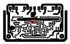
Just finished my layout using the mentioned Toshiba transistor for VAS.
I post my layout but size vise the will be a bit larger PC board
Because of GB started and I want to respect 🙂 other peoples work and desire I can not afford any support if you chose my layout which will be home made and iron transferred.
I only chose to do it these way these will feet my heatsink well.
Otherwise I would participate in GB.
Greetings
Attachments
The 2SC3423 and 2SA1360 look very suitable but as with all semiconductors, make sure you can buy them from a reputable supplier. I just checked Farnell, RS and Mouser in the UK and only Farnell have them but with a £16.00 one off charge to source them from USA stock.
Don't risk buying unknown stock from non recognised suppliers.
Edit... even that's not correct... the Farnell site diverted to a different NTE part. So no good.
Don't risk buying unknown stock from non recognised suppliers.
Edit... even that's not correct... the Farnell site diverted to a different NTE part. So no good.
These guy sell them but I would not put my hand in the fire..
http://www.analogmetric.com/
Again I have some left over from several years from another project.
http://www.analogmetric.com/
Again I have some left over from several years from another project.
Last edited:
It is almost impossible to do that, may be double sided PC boards with (some)SMD part.
Incredible amount of work!
Just finished my layout using the mentioned Toshiba transistor for VAS.
I post my layout but size vise the will be a bit larger PC board
Because of GB started and I want to respect 🙂 other peoples work and desire I can not afford any support if you chose my layout which will be home made and iron transferred.
I only chose to do it these way these will feet my heatsink well.
Otherwise I would participate in GB.
Greetings
Hello,
Very nice layout indeed and doing it in paint really requires tonnage of patience and carefulness. Congratulations!.
There is no problem if people want to use my layout (or your layout) for iron transfer, thats why I posted bottom and silk and grey.
I want most people to give it a try because, as informed by AKSA music is not defined by very very low THD or ultra high slewrate alone.
Thank you.
I agree with you, these amp deserve a try. Thanks to Mooly! 🙂
Thank you.
I agree with you, these amp deserve a try. Thanks to Mooly! 🙂
pl connect the trimmer on your layout like this after assembling.
Attachments
Interest
current interest list.
1. Rick G.-1pair (confirmed)
2. joshvi-1pair (confirmed)
3. gannaji-1pair (confirmed)
4. av-trouvaille-3 pair (confirmed)
current interest list.
1. Rick G.-1pair (confirmed)
2. joshvi-1pair (confirmed)
3. gannaji-1pair (confirmed)
4. av-trouvaille-3 pair (confirmed)
- Home
- Amplifiers
- Solid State
- My MOSFET amplifier designed for music