Hi, Mooly
didik wiryawan is a diyAudio Member look at page 28,
and has a web site of a JFET-MOSFET Power Amplifier based on the Goldmund Mimesis3
called MP50Di , it seems interesting...
didik wiryawan is a diyAudio Member look at page 28,
and has a web site of a JFET-MOSFET Power Amplifier based on the Goldmund Mimesis3
called MP50Di , it seems interesting...
Thanks 🙂
Page 28 ? You would have to give a post number or link as everyone sees different depending on settings. This is page 22 for me 😀
Page 28 ? You would have to give a post number or link as everyone sees different depending on settings. This is page 22 for me 😀
Look at post1. It confirms what this Thread is about.
If you want a different schematic from didk, then start a new Thread.
If you want a different schematic from didk, then start a new Thread.
How is set the bias current? How many mA?
R8 in the circuit in post #1
Initially you can fit a preset (470 or 1000 ohm) and adjust for 100ma in the output FETs. Then replace the preset with fixed resistor.
Very interesting... Just would like to find the source of those PCBs...That's good. You won't be disappointed 🙂Hi Mooly,
For now I print the pdf layout by alexmm. I want to build this one. Thank you for this design.
Regards,
Boyet
Very interesting... Just would like to find the source of those PCBs...
It's just the layout, no physical boards were available unless you etched them yourself.
I've found this good project, I'm interested in Fet and MosFet applications.
🙂
I've created the spice model in MultiSim of the amp.
Three questions, this is the first.
One is about R27 and the current that flows in D1.
If the value of R27 is 10K the Zener diode is not polarized and IC1 works with a not stabilized DC of about 7 Volts.
In order to have about 20mA that flows through D1 it's required a 1.2k for R27.
This consideration if valid if the not stabilized DC supply to IC1 is unintentional.
It there are other reasons please let me know.
🙂
🙂
I've created the spice model in MultiSim of the amp.
Three questions, this is the first.
One is about R27 and the current that flows in D1.
If the value of R27 is 10K the Zener diode is not polarized and IC1 works with a not stabilized DC of about 7 Volts.
In order to have about 20mA that flows through D1 it's required a 1.2k for R27.
This consideration if valid if the not stabilized DC supply to IC1 is unintentional.
It there are other reasons please let me know.
🙂
Thanks for the interest, and an interesting question 🙂
Simulating this can be tricky because "real world" and "simulation" often vary significantly. You might find the simulated opamp draws much more current than a real TL071 would in practice. The values on the circuit are correct for a TLO71 and -45 volt unregulated rail with the zener only needing a couple of milliamps to give a stable rail. The loading on the TL071 output means it only has to deliver a couple of hundred microamps at most.
Simulating this can be tricky because "real world" and "simulation" often vary significantly. You might find the simulated opamp draws much more current than a real TL071 would in practice. The values on the circuit are correct for a TLO71 and -45 volt unregulated rail with the zener only needing a couple of milliamps to give a stable rail. The loading on the TL071 output means it only has to deliver a couple of hundred microamps at most.
Thanks for the interest, and an interesting question 🙂
Simulating this can be tricky because "real world" and "simulation" often vary significantly. You might find the simulated opamp draws much more current than a real TL071 would in practice. The values on the circuit are correct for a TLO71 and -45 volt unregulated rail with the zener only needing a couple of milliamps to give a stable rail. The loading on the TL071 output means it only has to deliver a couple of hundred microamps at most.
Ha ha, interesting reply.
This make my further questions not useful.
🙂
OK, but ask away if you are not sure.
(and I haven't got all the answers or might have missed something... so ask 🙂)
(and I haven't got all the answers or might have missed something... so ask 🙂)
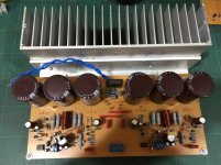
Ah, brilliant, excellent job. I like the heatsink 🙂
(Do let us know what you think of the performance... and don't forget to include a speaker relay delay... it needs it because of the single ended input + servo)

(Do let us know what you think of the performance... and don't forget to include a speaker relay delay... it needs it because of the single ended input + servo)
Hello Zoltar and Gavivina,hi didik
when are you going to update the new circuit on your website.Because you said so !
i am also waiting
Thank you for your interest on my MP50Di which is based on GoldMund Mimesis3 with minor modified/improvement on bias setting in the differential and upgrade it to run class A. Now I am doing update the article after friend of mind helped me to fix my web which was hacked. During it was hacked, the bandwidth quota was always exceeded, so that I could not do anything.
By The way, Gavivina my friend from Ghana who got already the PCB, how does it sound despite you operate it in class AB ?
Most of Audiophile friends of mine in Jakarta agree that MP50Di class A sounded musical, good staging and depth, power full bass, it even sounded better that the Mimesis 3. -🙂 😀
Last edited:
Ah, brilliant, excellent job. I like the heatsink 🙂
(Do let us know what you think of the performance... and don't forget to include a speaker relay delay... it needs it because of the single ended input + servo)
Hi Karl,
Have hooked up for testing. Speaker protect/delay included.
At initial start up, dc offset starts at about 50 mV and settles down to some
3 to 5mV. Running for about half an hour, the heatsink is only warm at touch.
There is very slight hiss and hum. Probably due to messy wiring.
Playing Jennifer Warns - (Hunter/way down deep), the bass is very precise and well controlled. Rich soundstage and the vocals are best so far. Have built the P3A with similar layout and all is similar performance in terms of dynamic and attack. But this is subjective to my setup, your amp excels in the vocals. Highs are well detailed and sweet. Overall I like it very much.
For a simple circuit, it is worth the build.

That's a really neat build you have there 🙂
I'm pleased your liking the audio presentation, and I know others that have built it have had similar findings.
What can I say 🙂 Great ! well done.
I'm pleased your liking the audio presentation, and I know others that have built it have had similar findings.
What can I say 🙂 Great ! well done.
- Home
- Amplifiers
- Solid State
- My MOSFET amplifier designed for music