Corrected (add pad for C1 WIMA MKS4).
alex mm thank you for PCB Concept
I'm starting to work.
I can not add files to the forums >devil<- can be found at:
http://tinyurl.com/64ovwed
alex mm thank you for PCB Concept
I'm starting to work.
I can not add files to the forums >devil<- can be found at:
http://tinyurl.com/64ovwed
Have you read all the original thread ? regarding bias adjustment and testing without FET's fitted. The opamp must be a TL071 type.
Any problems just ask 🙂
Any problems just ask 🙂
Hi and thanks for the interest. I haven't tried a quasi output stage, but you are correct, they have a very good reputation in some circles for sonics. Why don't you try it 🙂
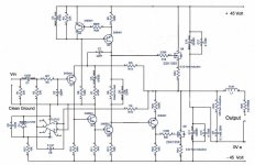
Also perhaps try with an NPN driver for the upper MOSFET as the current through the CCS Q3 is only around 6ma.
----------------------------------------------------------------------------------------------------------
The design as presented is fully worked and tested and owes a lot to the use of the single ended input stage for its sonic qualities.
Mooly quasi amplifier
Hi Mooly.
I can not develop the design of the amplifier because I'm not technical. I'm just an amateur to build amplifiers. Your amplifier is interesting and I just wanted to give you an idea.
Thanks
Hi Mooly.
I can not develop the design of the amplifier because I'm not technical. I'm just an amateur to build amplifiers. Your amplifier is interesting and I just wanted to give you an idea.
Thanks
Hi .
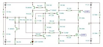
I have red all comments , and what can I sey ,thank you for the nice words . Another PCB revised 😉 http://i26.tinypic.com/2el8e92.jpg
this time better 😀 regards alex
Hi Alex MM !
Please, if you are able making PCB by this schematic!?
thanks and cheers !
Attachments
radio, what's up with you? I found that you requested Alex for a PCB design for this same amp here in this thread, LazyCat's SSA thread and this thread http://www.diyaudio.com/forums/solid-state/194871-pcb-quasi-amplifier-beginners-changes.html. The last one is a thread started by you and please confine your specific request to that thread. Thanks.
Just to bring this thread back on track I have recently replaced the output relays with a solid state version. All credit for that idea goes to the folk in this and another thread,
http://www.diyaudio.com/forums/solid-state/191449-output-relays-13.html#post2659578
http://www.diyaudio.com/forums/solid-state/191449-output-relays-14.html#post2660474
http://www.diyaudio.com/forums/solid-state/191449-output-relays-13.html#post2659578
http://www.diyaudio.com/forums/solid-state/191449-output-relays-14.html#post2660474
I'm looking and looking.
I guess I choose your solution.
On the basis of PCB alex-mm - my version.
DipTrace PCB files:


DEAR SIR,
I AM NEW in electronics plz send me the software by which i open your this dip zip file thank you.
Hi Mooly,
nice job.
However, with R17, R22 1k5, it is impossible to have 'heavily bias class AB' Isn't it ?
Why don't you reduce the R17,R22 to just several ohm, for instance 82ohm? You can run with 250mA bias on the mosfet or even 700mA but with decreasing the supply rail to 24-30V (max).
You can feel the different sounding with higher/heavily
Thanks for the kind words didik.
The design evolved to its final form both after much listening and also testing. The case and construction method using the "cans + heatsinks" put a limit on what was possible dissipation wise but the design works (sounds) really good as it is.
thanks for the interest 🙂
The design evolved to its final form both after much listening and also testing. The case and construction method using the "cans + heatsinks" put a limit on what was possible dissipation wise but the design works (sounds) really good as it is.
thanks for the interest 🙂
Attachments

Hi Mooly, yes I agreed with you, trust 'our own ears' .
Sorry, it was a mistake, I meant with the R17, R22 1K5, it is not pretty sure that the driver will run at its sweet spot caused by possibly too low of Q current. The mosfets of course can run hot even in pure class A but not for the driver. Please correct me if I am wrong.
With this current conditions, your amplifier has sounded very good but you can probably make it sounds much better. 🙂
I designed JFET-MOSFET amplifier based on GoldMund Mimesis3 but with some changes according to my taste. I will upload it later.
Last edited:
- Home
- Amplifiers
- Solid State
- My MOSFET amplifier designed for music