Hi warrjon,Magnetic Sleeve? this is what I'm endeavoring to incorporate into the SP10 DD motor
I am not using a sleeve of any kind. I am using a modified vee-block instead. The platter is supported by a spherical thrust bearing whose center line is located at the center of gravity of the rotating mass as previously discussed. The above-mentioned vee-block only supports the side-force of the platter shaft.
The spherical bearing and the vee-block are housed in the bearing housing which is sealed so that it can be filled with way oil if the need arises.
Sincerely,
Ralf
Hi warrjon,
I found and adjusted the COG of the complete rotating assembly with the help of my CAD program.
The spindle diameter is .625". The spindle is not going to be used to locate the LP record. I am going to use a separate click-adjustable locating pin for that purpose.
Hi,
Spindle diameter almost 16mm. To my little experience is a bit too big. My best result was accomplished with 13mm spindle diameter. However may depends on the type of sleeves used as well.
Rgds
Adelmo
Last edited:
Hello everyone,
Last year, when I assembled the improved version of my tangentially tracking tone arm. I ran into a problem with its servo circuitry. I decided to stop working on the tone arm for a while and to start working on my long-neglected turn table instead.
When I started this thread, I didn't want to give away the principle upon which my turn table design was based because I didn't want some troll (you know who you are) to tell me "You learned that wrong". Also, in order to test the bearing principle, the platter has to be rotating steadily so that one's hands are free to operate the tools for testing, such as a force gauge and or a dial test indicator.
I wanted to design a "Zero Clearance" platter bearing system that was based on gyroscopic precession. In my youth, I became fascinated by guns when I was 10 years old and by guitars soon after and by gyroscopes in my late twenties. I have a small but neglected collection of various types of gyroscopic instruments of which a Sperry Mark 14 gyro compass from world war two is the most desirable part. That compass uses the rotation and gravity of Planet Earth to align itself with True North.
I am now in the process of testing my bearing principle. I have the motor to drive the platter and I devised a method to test the functioning of the bearing.
The Delrin platter consists of two vertically separable halves, each containing six lead weights. Attached to the underside of the platter is an 8" diameter aluminum disk and a 5/8" diameter aluminum shaft extending upwards through the platter and approximately 4" downward from the platter. The whole assembly rests on a set of spherical thrust bearings, seated in the top of an aluminum bearing housing. The bottom of the bearing housing is sealed so that the entire bearing assembly may be operated completely submerged in lubricating oil.
In order to prevent the spherical thrust bearing to tilt the platter away from the horizontal, the bottom end of the platter shaft is located by two rotatable bronze bearings, functioning as an articulated vee-block. There is a third identical bronze bearing which closes the open side of the vee-block to prevent the platter from tilting when it is not rotating. That third bronze bearing clears the platter shaft by .005" when the platter is rotating. The bearing housing is rotatably suspended by the foot assembly of the turn table and it must be oriented to True North. The magnetic deviation from True North for every location where Humans live is available on the internet. When the turntable platter rotates, the Earth's rotation precesses the bottom end of the platter shaft to seat in the articulated vee-block thereby creating a "Zero Clearance" platter bearing. There!
Sincerely,
Ralf
Attachments

Hello rayma,
Please read my post again. I had forgotten to include two drawings.
Even though Firebaugh and I, have the same design goal, our solutions are completely different.
My bearing will work as a belt drive and as a direct drive while Firebaugh's works with as a belt drive only.
Sincerely,
Ralf
Please read my post again. I had forgotten to include two drawings.
Even though Firebaugh and I, have the same design goal, our solutions are completely different.
My bearing will work as a belt drive and as a direct drive while Firebaugh's works with as a belt drive only.
Sincerely,
Ralf
Over the years of my interest in Platter Bearing Design, I have shown a interest in what can be done, against what is typically supplied.
On the 90's I may have been one of Martin Bastin's first customers for his 401 Bearing Mod'.
Many discussions on bearings since and the witnessing of designs for Platter Bearings being incorporated on TT's I am quite familiar with.
I once more entered the arena of concept and recently sent out a design for review of a Bearing for a well known DD TT to a engineer friend who lives and breathes TT's and TA's. It seems my proposal was very much on the right path, and the usual constraints met had been overcome through a change of design for the TT's function.
It is nice to see that others are also pondering their thoughts over a ling period of time on how a Platter can benefit from the interface with the Bearings design and assembly.
Seeing these thoughts on paper is a milestone.
Hello JohnnoG,
Thanks to a fellow platter bearing enthusiast.
The PNG drawings I uploaded look kind of faint and I would like to replace them with the original PDF versions.
If the PDF versions look better, maybe Mr. rayma could replace the PNGs in post #163 with the PDFs in THIS post?
Sincerely,
Ralf
Thanks to a fellow platter bearing enthusiast.
The PNG drawings I uploaded look kind of faint and I would like to replace them with the original PDF versions.
If the PDF versions look better, maybe Mr. rayma could replace the PNGs in post #163 with the PDFs in THIS post?
Sincerely,
Ralf
Attachments
"The Delrin platter consists of two vertically separable halves, each containing six lead weights."
Ralf, may I ask.
What do you see as the advantage of this construction over a homogenous disc, it seems to me to add complexity and the prospect of being out of balance. (Obviously it could be dynamically balanced, but why bother in the first place?). Is it's main function not just to act as a flywheel?
Delin is lighter than Aluminum.
Lead is for weight, for reduced speed variation.
There are equations for speed and variation, look them up.
Lead is for weight, for reduced speed variation.
There are equations for speed and variation, look them up.
He is asking why there are two platters - not about lead weights. I suspect the two pieces dissipate energy more quickly that one large mass.
Just a comment.Hello rayma,
Please read my post again. I had forgotten to include two drawings.
Even though Firebaugh and I, have the same design goal, our solutions are completely different.
My bearing will work as a belt drive and as a direct drive while Firebaugh's works with as a belt drive only.
Sincerely,
Ralf
In at least one of Firebaugh's embodiments, the vertical thrust bearing is offset from the axis of rotation. This ensures that the thrust bearing is correctly lubricated. However it also provides an offset drag force which can be used to stabilise the shaft even without using a belt drive. In theory (and patent?) this provides enough stability for direct-drive applications as well.
Cheers, Mike
Hello jotom750:"The Delrin platter consists of two vertically separable halves, each containing six lead weights."
Ralf, may I ask.
What do you see as the advantage of this construction over a homogenous disc, it seems to me to add complexity and the prospect of being out of balance. (Obviously it could be dynamically balanced, but why bother in the first place?). Is it's main function not just to act as a flywheel?
The overriding reason for choosing the particular construction details for my turntable is that, I have to have "some" mechanism to support the testing of my "Zero Clearance" bearing concept. I am not introducing a whole new turntable concept but just a new central bearing principle. There are many ways of constructing a weighted platter, and I used this particular design not because it is better, but it was all I could think of at the time.
Sincerely.
Ralf
Hello Mike,Just a comment.
In at least one of Firebaugh's embodiments, the vertical thrust bearing is offset from the axis of rotation. This ensures that the thrust bearing is correctly lubricated. However it also provides an offset drag force which can be used to stabilise the shaft even without using a belt drive. In theory (and patent?) this provides enough stability for direct-drive applications as well.
Cheers, Mike
Thanks for commenting.
I have only read one of Mr. Firebaugh's patents and I'll make it a point to find and read his other patents.
Sincerely,
Ralf
Hi Ralf, please don’t take my post as criticism - you’re doing a fine job of exploring and doing. Just trying to help with the inspiration. Keep up the good work!
Cheers,
Mike
Cheers,
Mike
Hello Mike,
No problem, I didn't take your post as criticism.
Sincerely,
Ralf
No problem, I didn't take your post as criticism.
Sincerely,
Ralf
Hello everyone,
I am making progress. I just finished machining the components for supporting the motor which I will use to finally drive my turn table.
I am attaching a PDF CAD drawing of what that looks like.
However, there is one little problem; I need help to wire the motor to the AC line. For that purpose, I am attaching a PDF CAD drawing identifying the four colored wires coming out of the motor.
Sincerely,
Ralf
Attachments
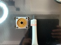
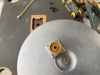
This is from my versa dynamics tt and uses a similar concept of a ceramic ring on a hardened ring with a fluorocarbon
grease (nye 823a- expensive) and the round peg in a square hole idea - ala well tempered labs
I can’t say I liked the idea but it does provide rigidity in 2 directions and simply works in a weird kind of way
grease (nye 823a- expensive) and the round peg in a square hole idea - ala well tempered labs
I can’t say I liked the idea but it does provide rigidity in 2 directions and simply works in a weird kind of way
Attachments
This looks like your motor, just check with a multimeter.
https://i.ebayimg.com/images/g/bdsAAOSwVlFmcEsE/s-l1600.webp
https://i.ebayimg.com/images/g/bdsAAOSwVlFmcEsE/s-l1600.webp
Hello ralphfcooke,
Thank you for the perfect response. I'll have my turntable running by the end of the week.
Sincerely,
Ralf
Thank you for the perfect response. I'll have my turntable running by the end of the week.
Sincerely,
Ralf
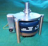
Well well, after a drawn-out comedy of errors I finally have an assembled motor and pulley to operate my turn table.
I encountered the following group of obstacles to get me to the finished motor:
1) I had saved a 300 RPM Beau inside-out motor for almost fifty years for my turn table project.
2) I misread the motor's label and mistakenly connected it to a 11.5MF run capacitor.
3) The motor ran hot and started to vibrate.
4) looking at the motor's label again, I discovered that the motor's run capacitor should have been 1.5MF.
5) Thinking that, I destroyed the motor, I purchased a replacement motor off e-bay, running at 450RPM.
6) The guy selling the motor on e-bay, sent the wrong motor and it took two weeks to get that straightened out.
7) the motor was well made but I didn't like the method of attaching it to the intended equipment, like a tape deck or in my case, a turn table.
8) I designed a "better" method of mounting the motor to suit my application.
So, after the above was taken care of, I needed to design and make a pulley for that motor.
I was adamant to not use set screws to fix the pulley to the motor shaft because the set screws would pull the pulley off center to the motor shaft.
Being an incorrigible inventor, I devised a method of attaching the pulley to the motor shaft without using set screws.
When I worked in aircraft machine shops in Connecticut, I remembered the shrink fit method that was used to fit parts together, you know, heating the female part in boiling water and cooling the male part in dry ice method. (please, no wise cracks) That worked quite well of course, except, if you wanted to disassemble those two parts.
So, I came up with my own reversible shrink fit method: I designed a pulley for 331/3 and 45 RPM with one end of the pulley having a hub with a .375" diameter through hole for clamping to the motor shaft. Then I drilled three equally spaced .199" diameter holes into the face of the pulley's hub so that they would intersect with the hole for the motor shaft and would leave a .030" wall between them and the outside diameter of the pulley's hub. Finally, I drilled and threaded three equally spaced holes into the circumference of the pulley's hub, intersecting the bore for the motor shaft.
Next, I designed and made a tool that I call an expansion collar. This tool is placed around the pulley's hub, and the hub is expanded using three 10-32 socket head cap screws. Once the hub has been expanded approximately .003", the pulley is slid onto the motor shaft and the screws of the expansion tool are loosened, causing the pulley's hub to tightly grip the motor shaft and of course the whole process is reversible.
The attached pictures and PDFs probably explain the idea a little better than my writings.
.


Sincerely,
Ralf
I encountered the following group of obstacles to get me to the finished motor:
1) I had saved a 300 RPM Beau inside-out motor for almost fifty years for my turn table project.
2) I misread the motor's label and mistakenly connected it to a 11.5MF run capacitor.
3) The motor ran hot and started to vibrate.
4) looking at the motor's label again, I discovered that the motor's run capacitor should have been 1.5MF.
5) Thinking that, I destroyed the motor, I purchased a replacement motor off e-bay, running at 450RPM.
6) The guy selling the motor on e-bay, sent the wrong motor and it took two weeks to get that straightened out.
7) the motor was well made but I didn't like the method of attaching it to the intended equipment, like a tape deck or in my case, a turn table.
8) I designed a "better" method of mounting the motor to suit my application.
So, after the above was taken care of, I needed to design and make a pulley for that motor.
I was adamant to not use set screws to fix the pulley to the motor shaft because the set screws would pull the pulley off center to the motor shaft.
Being an incorrigible inventor, I devised a method of attaching the pulley to the motor shaft without using set screws.
When I worked in aircraft machine shops in Connecticut, I remembered the shrink fit method that was used to fit parts together, you know, heating the female part in boiling water and cooling the male part in dry ice method. (please, no wise cracks) That worked quite well of course, except, if you wanted to disassemble those two parts.
So, I came up with my own reversible shrink fit method: I designed a pulley for 331/3 and 45 RPM with one end of the pulley having a hub with a .375" diameter through hole for clamping to the motor shaft. Then I drilled three equally spaced .199" diameter holes into the face of the pulley's hub so that they would intersect with the hole for the motor shaft and would leave a .030" wall between them and the outside diameter of the pulley's hub. Finally, I drilled and threaded three equally spaced holes into the circumference of the pulley's hub, intersecting the bore for the motor shaft.
Next, I designed and made a tool that I call an expansion collar. This tool is placed around the pulley's hub, and the hub is expanded using three 10-32 socket head cap screws. Once the hub has been expanded approximately .003", the pulley is slid onto the motor shaft and the screws of the expansion tool are loosened, causing the pulley's hub to tightly grip the motor shaft and of course the whole process is reversible.
The attached pictures and PDFs probably explain the idea a little better than my writings.
.
Sincerely,
Ralf
Attachments
Last edited:
- Home
- Source & Line
- Analogue Source
- My "maybe" revolutionary turntable design