With your next post saying you are pleased with what you have wrought - give us an idea of the potential of your tonearm being made available.
You are an inspiration to audio tweakers and music listeners. Wish my head had as much of the premium grey matter as yours.
You are an inspiration to audio tweakers and music listeners. Wish my head had as much of the premium grey matter as yours.
Hi rickmcinnis and Others,
I finally have some progress to report. After having ordered all of my raw materials, I had to wait for my friend's CNC machine to become available. He works full time and has to take a day off from work to be present when I use his machine. We both took the CNC semester at the local Yavapai community college, but if you don't operate the machine eight hours a day it takes a while to remember all you have learned.
The first parts to be machined were, the top and bottom halves of the Delrin platter. Firstly, I cut the platter halves into an octagon shape which turned out to be a mistake because it reduced the area available for clamping. In order to center the platter halves in the CNC machine, I would have had to indicate around the octagon of the platter. Knowing that that would be cumbersome, I reamed a 9/16" hole into the center of the platter in my own Bridgeport milling machine at home. It is easier to bend over a Bridgeport when indicating and centering a 12" octagon than it is in a HAAS CNC machine because the machine table of the HAAS can't be brought very close to the front of the machine. When the bottom half of the platter was all clamped and set up ready to go, I discovered that I left my USB stick at home. It had the CNC program on it. After an hour and a half round trip to get the USB stick we were finally ready to machine. All in all it took us all day to machine the two platter halves. They came out perfect and I am pleased.
The next step is to fly-cut them on all four sides in my Bridgeport milling machine.
This is the only CNC work that needed to be done. Everything else is milling and turning work. Therefore, my project should progress a little faster from here on.
Picture 1 shows the 9/16" hole being reamed into the center of the platter.
Picture 2 shows that hole being indicated in the HAAS CNC machine.
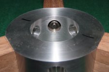
Picture 3 shows the six segmented pockets machined into the platter.
Those pockets will be filled with #12 lead shot and bee's wax during final assembly.
Sincerely,
Ralf


I finally have some progress to report. After having ordered all of my raw materials, I had to wait for my friend's CNC machine to become available. He works full time and has to take a day off from work to be present when I use his machine. We both took the CNC semester at the local Yavapai community college, but if you don't operate the machine eight hours a day it takes a while to remember all you have learned.
The first parts to be machined were, the top and bottom halves of the Delrin platter. Firstly, I cut the platter halves into an octagon shape which turned out to be a mistake because it reduced the area available for clamping. In order to center the platter halves in the CNC machine, I would have had to indicate around the octagon of the platter. Knowing that that would be cumbersome, I reamed a 9/16" hole into the center of the platter in my own Bridgeport milling machine at home. It is easier to bend over a Bridgeport when indicating and centering a 12" octagon than it is in a HAAS CNC machine because the machine table of the HAAS can't be brought very close to the front of the machine. When the bottom half of the platter was all clamped and set up ready to go, I discovered that I left my USB stick at home. It had the CNC program on it. After an hour and a half round trip to get the USB stick we were finally ready to machine. All in all it took us all day to machine the two platter halves. They came out perfect and I am pleased.
The next step is to fly-cut them on all four sides in my Bridgeport milling machine.
This is the only CNC work that needed to be done. Everything else is milling and turning work. Therefore, my project should progress a little faster from here on.
Picture 1 shows the 9/16" hole being reamed into the center of the platter.
Picture 2 shows that hole being indicated in the HAAS CNC machine.
Picture 3 shows the six segmented pockets machined into the platter.
Those pockets will be filled with #12 lead shot and bee's wax during final assembly.
Sincerely,
Ralf

Hi rickmcinnis,With your next post saying you are pleased with what you have wrought - give us an idea of the potential of your tonearm being made available.
You are an inspiration to audio tweakers and music listeners. Wish my head had as much of the premium grey matter as yours.
When I built my tone arm, I also made simple but accurate fixtures to make the various parts. Making more tone arms would be simpler but quite expensive because of the assumed low quantities.
As far as "gray matter" is concerned, I think it is more a matter of perseverance. You got to pick a project and then stick with it, "come hell or high water"!
Sincerely,
Ralf
Looks good Ralf.
How are you planning to find the COG of the platter, calculation or measurement?
What diameter spindle 8mm?
When I make Acetal platters I always put a 9/32 hole in the POM first and then everything is referenced from this. I have a fixture on my lathe faceplate with a 9/32 pin that's a very snug fit. It's easy with SP10mk2 platters because I can use the platter hold down bolts to fix the POM to the faceplate. I'm still working on a fixture to hold the inverted bearing platter in the lathe.
Hi warrjon,Looks good Ralf.
How are you planning to find the COG of the platter, calculation or measurement?
What diameter spindle 8mm?
When I make Acetal platters I always put a 9/32 hole in the POM first and then everything is referenced from this. I have a fixture on my lathe faceplate with a 9/32 pin that's a very snug fit. It's easy with SP10mk2 platters because I can use the platter hold down bolts to fix the POM to the faceplate. I'm still working on a fixture to hold the inverted bearing platter in the lathe.
I found and adjusted the COG of the complete rotating assembly with the help of my CAD program.
The spindle diameter is .625". The spindle is not going to be used to locate the LP record. I am going to use a separate click-adjustable locating pin for that purpose.
Sometimes that "perspiration" requires lots of inspiration that is denied to most. Especially those with the mediocre grey stuff.
When you say "click adjustable spindle" is this to compensate for records with misaligned "center" holes?
Does this mean you think the possibility of making your tonearm available unlikely?
When you say "click adjustable spindle" is this to compensate for records with misaligned "center" holes?
Does this mean you think the possibility of making your tonearm available unlikely?
Hi rickmcinnis,When you say "click adjustable spindle" is this to compensate for records with misaligned "center" holes?
Does this mean you think the possibility of making your tonearm available unlikely?
To your first question, yes. Designing a click-adjustable spindle was the easy part. Finding out how many clicks it would take to center a given eccentric LP, is going to be the tricky part. I'll solve that problem, or else, and it will be simpler than that $4,000 gadget described in another thread.
As to my tangentially tracking tone arm, I would consider making one at a time for a customer but as I said, it would be expensive.
Sincerely,
Ralf
Most TT spindles are 0.281" and the minimum RIAA hole spec is 0.284" so I make my spindles 0.2845" yes some LPs are tight but it reduces eccentricity. I have very few LPs where I can see the eccentricity and it's easy to implement.
Hi everyone,
It has been some time since I last posted.
I am now able to post recent progress because my friend’s lathe became available to me while he was building a garage.
I took nineteen pictures with a description for each below.
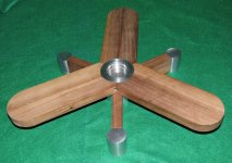
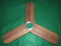
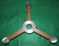
1) This shows the leg assembly with a “pod” at the end of each leg. The pods will contain spring-loaded feet using plastic Belleville disk springs. The cylindrical part at the center receives the main bearing. The legs are made from black American Walnut.
2) Ditto.
3) Ditto.
4) This shows the tone arm support assembly. It pivots around the top part of the bearing housing. The individual tone arm boards are also made from black American Walnut.
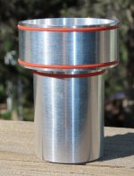
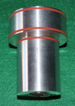
5) This shows the main bearing housing. It fits into the center of the leg assembly.
6) Ditto
7) This shows the Leg and tone arm support assembly. The main bearing housing is used to align the two assemblies.
8) Ditto.
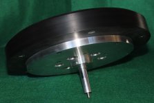
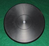
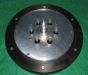
9) This shows the platter assembly. The platter consists of upper and lower halves, filled with six lead weights near the inside periphery. The aluminum plate under the platter acts as a stiffener just in case the Delrin platter decides to warp. The six large holes in the aluminum plate are used to adjust the location of the center of gravity of the platter assembly.
10) Ditto.
11) Ditto.
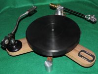
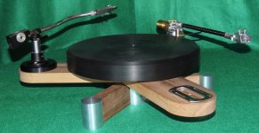
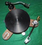
12) This shows the complete turntable assembly. There are still parts missing and the tone arms shown, are just sitting there, no screws.
13) Ditto.
14) Ditto.
15) Ditto.
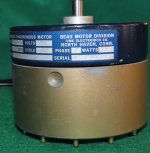
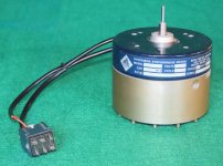
16) This shows the motor I intend to use. It is a hysteresis-synchronous capstan motor made by the Beau Motor Division of Umc Electronics, in North Haven Connecticut, where I used to live. It is an inside-out motor. It probably is over kill but that is all I have at the moment. I am in contact with Maxon and Micro-Mo to see what they have to offer. I am also going to contact Papst because they have small inside-out motors available.
17) Ditto.
18) Ditto.
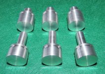
19) This shows the lathe blanks from which I am going to machine the foot assemblies.
If there are questions, please ask me.
Sincerely,
Ralf
It has been some time since I last posted.
I am now able to post recent progress because my friend’s lathe became available to me while he was building a garage.
I took nineteen pictures with a description for each below.
1) This shows the leg assembly with a “pod” at the end of each leg. The pods will contain spring-loaded feet using plastic Belleville disk springs. The cylindrical part at the center receives the main bearing. The legs are made from black American Walnut.
2) Ditto.
3) Ditto.
4) This shows the tone arm support assembly. It pivots around the top part of the bearing housing. The individual tone arm boards are also made from black American Walnut.
5) This shows the main bearing housing. It fits into the center of the leg assembly.
6) Ditto
7) This shows the Leg and tone arm support assembly. The main bearing housing is used to align the two assemblies.
8) Ditto.
9) This shows the platter assembly. The platter consists of upper and lower halves, filled with six lead weights near the inside periphery. The aluminum plate under the platter acts as a stiffener just in case the Delrin platter decides to warp. The six large holes in the aluminum plate are used to adjust the location of the center of gravity of the platter assembly.
10) Ditto.
11) Ditto.
12) This shows the complete turntable assembly. There are still parts missing and the tone arms shown, are just sitting there, no screws.
13) Ditto.
14) Ditto.
15) Ditto.
16) This shows the motor I intend to use. It is a hysteresis-synchronous capstan motor made by the Beau Motor Division of Umc Electronics, in North Haven Connecticut, where I used to live. It is an inside-out motor. It probably is over kill but that is all I have at the moment. I am in contact with Maxon and Micro-Mo to see what they have to offer. I am also going to contact Papst because they have small inside-out motors available.
17) Ditto.
18) Ditto.
19) This shows the lathe blanks from which I am going to machine the foot assemblies.
If there are questions, please ask me.
Sincerely,
Ralf
Attachments
-
 11_Platter_assy.JPG360 KB · Views: 235
 -
 12_Turntable_Tonearm_assy.JPG611.6 KB · Views: 214
 -
 13_Turntable_Tonearm_assy.JPG420.7 KB · Views: 214
 -
 14_Turntable_Tonearm_assy.JPG653.3 KB · Views: 222
 -
 16_Motor.JPG573 KB · Views: 230
 -
 18_Motor.JPG462.9 KB · Views: 237
 -
 10_Platter_assy.JPG598.9 KB · Views: 213
 -
 9_Platter_assy.JPG615 KB · Views: 220
 -
 7_Leg_and_Tone_Arm_Support_assy.JPG717 KB · Views: 211
 -
 6_Bearing_Housing_assy.JPG440.7 KB · Views: 219
 -
 5_Bearing_Housing_assy.JPG566.5 KB · Views: 219
 -
 4_Tone_Arm_Support_assy.JPG753 KB · Views: 219
 -
 3_Leg_Close_Up_assy.JPG249.9 KB · Views: 207
 -
 1_Leg_assy.JPG956.6 KB · Views: 216
 -
 19_Foot_Blanks.JPG678.7 KB · Views: 235
Is there anything you cannot do?
No doubt you subscribe to the "best plinth is almost a nonexistent plinth" school of thought.
It all looks so well conceived. Obviously lots of experience is reflected in what you have made.
That is quite a serious motor. What will you use to power it?
I have recently converted my system to "pure sine wave" inverters. The AC stays extremely steady with these. I think you should consider using one of those to generate your AC for the motor. Unless you are allergic to batteries and their fussiness.
Very impressive ... as if anyone is surprised by that.
Thanks for the update and the inspiration.
I tried to make a Foucault pendulum at work, suspending a lump of stainless steel on a thread from a (round) roof support, I found it fasinating to see evidence of the whole world rotating, but the way the thread looped around the roof support seemed to cause inaccuracies. I can vouch for lead being "difficult" to machine. Perhaps one or the reasons that lead isn't used is it's cheep, making it difficult to justify audiophile prices.
@Straight Tracker I have a couple of questions.
What are you using for the pivot point?
Are you running a full length sleeve or just a thin ring?
What are you using for the pivot point?
Are you running a full length sleeve or just a thin ring?
Hi rickmcinnis,Is there anything you cannot do?
No doubt you subscribe to the "best plinth is almost a nonexistent plinth" school of thought.
It all looks so well conceived. Obviously lots of experience is reflected in what you have made.
That is quite a serious motor. What will you use to power it?
I have recently converted my system to "pure sine wave" inverters. The AC stays extremely steady with these. I think you should consider using one of those to generate your AC for the motor. Unless you are allergic to batteries and their fussiness.
Very impressive ... as if anyone is surprised by that.
Thanks for the update and the inspiration.
Thank you for your kind words.
Yes, I have difficulties making printed circuit boards.
My plinth design is based on the Micro Seiki DDX1000.
The motor runs on 117VAC once I figure out how to wire it.
I like the free-standing motor concept.
As I said, I will probably use a smaller motor once I figure out what brand and model to buy.
There will be more information coming. I am not finished by a long shot.
Sincerely,
Ralf
Hi warrjon,@Straight Tracker I have a couple of questions.
What are you using for the pivot point?
Are you running a full length sleeve or just a thin ring?
I hope you don't mind, but I would like to keep that to myself for a little while longer. It won't be any kind of sleeve bearing because, as you know, sleeves require some clearance. I want a zero-clearance bearing system.
My work should be progressing much faster now, because all the work that required my friend's machines is done.
Sincerely,
Ralf
Hi cracked case,I tried to make a Foucault pendulum at work, suspending a lump of stainless steel on a thread from a (round) roof support, I found it fasinating to see evidence of the whole world rotating, but the way the thread looped around the roof support seemed to cause inaccuracies. I can vouch for lead being "difficult" to machine. Perhaps one or the reasons that lead isn't used is it's cheep, making it difficult to justify audiophile prices.
Did you suspend the thread from a thrust bearing so that the Earth/building would not twist the string as they rotated?
Sincerely,
Ralf
I must confess, I had no idea that this was necessary. Since the thread spun the weight around for half an hour before it's twist found an equalibrium, I'd be surprised if this was the cause of the inaccuracy that developed after a few hours, but I'm willing to be corrected on this. I have to say, it was really interesting to see the weight swinging in a different direction after a few hours, and realising that the whole world, everything that I have ever seen and known, had rotated beneath my feet, an odd feeling, even when you've known about Earth's rotation since childhood.
Hi warrjon,
I hope you don't mind, but I would like to keep that to myself for a little while longer. It won't be any kind of sleeve bearing because, as you know, sleeves require some clearance. I want a zero-clearance bearing system.
My work should be progressing much faster now, because all the work that required my friend's machines is done.
Sincerely,
Ralf
Magnetic Sleeve? this is what I'm endeavoring to incorporate into the SP10 DD motor
So If I understand this correctly The center spindle is attached to a thread & hung from an apparatus & spins allowing you to play LP's & have no pressure on the thrust pad?
Cheers
Cheers
Hi DNic,So If I understand this correctly The center spindle is attached to a thread & hung from an apparatus & spins allowing you to play LP's & have no pressure on the thrust pad?
Cheers
cracked case's post was off-topic. It did not pertain to my turntable built.
At one time I thought of an arrangement as you describe. The string would have to be supported by a rotating bearing, so as not to twist the thread.
It would vibrate like a guitar string.
Sincerely,
Ralf
- Home
- Source & Line
- Analogue Source
- My "maybe" revolutionary turntable design