I have tested and used KSC3503/ KSA1381 and Philips BF series and also Sanyo Video transistors in both BJT and MOSFET version but MOSFET version donot require additional capacitor of 4.7pf but the BJT version need them to get clean output.The KSC3503 might be "too good": it has a Cob under 5pF, and depending on other components, it could result in instability.
This has already been observed with other BFxyz video transistors, but the remedy is very straightforward: a small additional capacitor, like 3p3 or 4p7.

Elvee, after building 2 of them, I'm trying to play with your Circlophone a little bit...
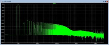
Here is a version with op-amp in the front. It shows very small distortion, high slew rate, and nice FFT profile.
I managed to make it handle square waves, and started working on stability (Phase Margin).
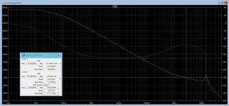
The final values are OK, but the OLG plots look little bit weird (at higher frequencies).
Could you give me some feedback about these modifications?
a) I had to remove RC network between collectors of the LTP transistors
b) had to add degeneration resistors in the emitters of the LTP
Without these changes, square waves were oscillating like crazy.
Does it make sense to go in this direction (with op-amp)? Not that there was anything wrong with the original amp, I listen to it a lot.
My goals were: lower distortions, increase slew rate, and bring all the harmonics under -120dB.
So far I've done sims only at 1kHz input (sinus/squares).

Here is a version with op-amp in the front. It shows very small distortion, high slew rate, and nice FFT profile.
I managed to make it handle square waves, and started working on stability (Phase Margin).
The final values are OK, but the OLG plots look little bit weird (at higher frequencies).
Could you give me some feedback about these modifications?
a) I had to remove RC network between collectors of the LTP transistors
b) had to add degeneration resistors in the emitters of the LTP
Without these changes, square waves were oscillating like crazy.
Does it make sense to go in this direction (with op-amp)? Not that there was anything wrong with the original amp, I listen to it a lot.
My goals were: lower distortions, increase slew rate, and bring all the harmonics under -120dB.
So far I've done sims only at 1kHz input (sinus/squares).
Attachments
This is very good news @minek123 . I was about to revive the thread by giving special thanks for the its creator: Elvee
I listen to it a lot too. I couldn't find a chance to make a good enclosure for it because of this. Hexfet version is my daily driver.
Did you see the CFP input version?
https://www.diyaudio.com/community/threads/my-little-cheap-circlophone-c.189599/post-2892032
It was a topic years back then and I have build one too... But we couldn't tame the overshoot issue with square wave by altering compensations. Otherwise, it was stable as original Circlophone. It was a BJT version. I didn't revise it with the Hexfet version. Maybe I should...
Mr Minek, Further improvement to the original Circlophone frame is a welcome move. Please also check it from the long term stability point of view.
Did you see the CFP input version?
https://www.diyaudio.com/community/threads/my-little-cheap-circlophone-c.189599/post-2892032
I somehow missed that one. Interesting.
I wanted to build hexfet circlophone too, but in this one I want to use metal can transistors (TO-3) - they will
be exposed and visible outside of the amp, that why I went with MJs.
There used to be TO-3 lateral fets from Profusion, but I think they are gone by now..
The Inverted J-FET Cirlophone by Piersma is really excellent in the bipolar version and fantastic in the mosfet version. I built both of them and they are my favorites in my workshop.
I still have a pair or two of PCBs if you want to try these versions I could send them to you by mail 🙂
https://www.diyaudio.com/community/threads/inverted-j-fet-circlophone-builders-thread.294338/
I still have a pair or two of PCBs if you want to try these versions I could send them to you by mail 🙂
https://www.diyaudio.com/community/threads/inverted-j-fet-circlophone-builders-thread.294338/
Very interesting development: it changes a mid-range amplifier into a super-amp, but with the ease and convenience of the C.Could you give me some feedback about these modifications?
Some annoying wrinkles remain, but it should be possible to iron them out. It is probably not going to be easy (I have already tried the usual tricks, to no avail), but it is certainly possible with persistence and creativity.
Watch this space, and everyone's ideas are welcome!
The measured SR of the original C (with 2N3055's) was 20/24 V/µs: https://www.diyaudio.com/community/threads/my-little-cheap-circlophone-c.189599/post-2583998
The simulated value was probably higher (but irrelevant).
Without the shunt compensation networks of the original, the improved version is bound to do better; however, the difficulty is to operate without them and still remain stable. Re-establishing them is not an option, since they degrade stability.
I suppose that the opamp acts partly as an active compensation, but it is not sufficient, even in sim. I suspect that a real-world circuit would be even worse. The solution is probably to enhance the active compensation effect, but at the moment I do not see how
I made several attempts to tune compensation, and LTP emitter degeneration resistors.
OLG plot looks better, without ugly kinks suggest oscillations.
Squares are not perfect, more tuning needed.
BUT - what worries me - I can see that small changes of few pFs here or there, makes big differences - which from my experience (spice vs real life)
indicates that real build might not be stable.....
Attachments
You may checkout @Nazar_lv 's precise opamp models. NE5534/5532 models have a good reputation.
https://www.diyaudio.com/community/threads/accurate-spice-macromodels-for-some-op-amps.337687/
https://www.diyaudio.com/community/threads/accurate-spice-macromodels-for-some-op-amps.337687/
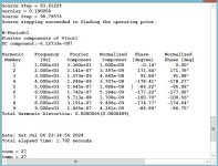
Very nice.Final version for today. All look good to me.
PM: 80, GM: 12, SR: 90
Squares and OLG plots look pretty good.
No tests above 1kHz yet.
The phase margin evolves in a very unusual way: at mid frequencies, 1~100kHz it shrinks to almost nothing.
In principle it doesn't really matter: what counts is the figure for unity gain, but at these frequencies, it close to a conditionally stable system which sometimes behave oddly, during the ramping up of the supplies or clipping for example.
Anyway, at this stage I think it is good enough to risk a physical prototype
The reasons I'm using LT 1056 in the sims -You may checkout @Nazar_lv 's precise opamp models. NE5534/5532 models have a good reputation.
https://www.diyaudio.com/community/threads/accurate-spice-macromodels-for-some-op-amps.337687/
a) it's a JFET op-amp (unlike NE)
b) its model it's built-in in LT Spice, so anybody can run sims without bothering to install op-amp models (which is pain in the neck)
c) it's a good op-amp
d) if amp sims well with it, it will most likely also work with TL 071 (cheap!), TLE 2071, TLE 2081
e) I built several amps with it, with good results
f) I have plenty of them in stock
This doesn't mean we shouldn't try other op-amps, but I'm afraid compensation values will have to be re-worked (most likely).
Feel free to do so.
Another observation - unlike original Circlophone, this one will be more picky in terms of selection of transistors.
If using different devices for VAS, drivers or outputs, most likely simulation will have to be re-done, and perhaps some compensation
RC components will have to be adjusted.
The devices I used in this sim are all currently in production (not obsolete yet) and fairly common.
But, selfishly, I choose them because I have them all in stock.
I'll spend more time on simulations (20kHz, clipping, perhaps improving shape of the phase margin plot, if possible, testing different devices).
Also, I can try the same approach but with hexfets; I suspect hexfet version might be even better than BJT.
As for prototyping, I hate doing breadboards or spider web of wires in the air, I always get something wrong 🙂
so I guess I'll design a PCB, and wait for it to arrive.
Also, I can try the same approach but with hexfets; I suspect hexfet version might be even better than BJT.
As for prototyping, I hate doing breadboards or spider web of wires in the air, I always get something wrong 🙂
so I guess I'll design a PCB, and wait for it to arrive.
Questions in my mind:
- If signal passes through a 16V/us opamp, how do we get 100V/us slew rate at the end?
- Is there a specific reason to use JFET opamp?
- What are the most important specs of the opamp in this configuration? (DC offset, noise, etc.)
- Is Opamp's Class B topology going to affect Amp's (semi) Class A topology?
- Do we benefit if we bias the opamp (1.5k resistor from output to negative rail) to force it to work in Class A?
Last edited:
Voltage swing on the opamp is small, so 16V SR is more than enough. VAS and output needs to provide much higher SR to accomodate rail to rail voltage swing.
Opamp doesn't have to, we are not using it as vas.
The higher voltage swing, the higher slew rate is needed.
1W amp doesn't need the same slew rate as 100W amp.
Reasons to use JFET op-amp:
a) high input impedance
b) low input bias current
c) low noise characteristics
d) good thermal stability
Good comparison on BJT and JFET op-amps:
https://www.ti.com/lit/ab/sboa355/sboa355.pdf
https://eelectronics.medium.com/exploring-the-features-of-jfet-input-op-amps-84773f3e4ebb
Last edited:
- Home
- Amplifiers
- Solid State
- ♫♪ My little cheap Circlophone© ♫♪