If you can bend the legs of the 2sk389, sure. I have a pair myself, but decided to use to92's (the 2sk369, basically a 2sk170, but intended for higher currents). My 389's were salvaged, so have very short legs, but i might improvise something if the 369's fail.
Thank you!!!The builder's thread for the Inverted J-FET Circlophone is up.
The location of that is here: http://www.diyaudio.com/forums/solid-state/294338-inverted-j-fet-circlophone-builders-thread.html <--link
A couple of the questions that I can field:
Bat86 is the go-to part here. Find some.
However, it is possible to replace a series combination of Bat+Standard with a series pair of 1A FR diodes, to achieve the approximately 1V sum.
Look for MBR diode with tolerances of 5a~10a and either 35v or 45v. SB schottky also works.
P.S.
Not mentioned is the clipper positioned across the inverting input coupler, which is less than 0.7v, even though it will conflict with the 1v sensor if either the inverting input coupler is too small or the non-inverting coupler is too large, in which case, the inverting input's coupler would also require the same 1v tolerance as the sensor. A problem of that sort is more likely to occur if the drivers are high gain while the outputs are low gain (or not linear enough, so that their gain drops when the workload increases). With the Standard Circlophone, the audible symptom is when you crank up the volume and the amp goes unexpectedly far louder and really warm/blurry (the higher gain small signal devices asked for more than they can do, meanwhile the outputs didn't help proportionately). It makes for outstandingly dynamic audio; however, a severe dose of that might annoy. Piersma's build may be immune because of specifying exactly which devices to use. I suggest to minimize substitutions.
Signal Schottky is the type:I also see I don't have some of the diodes, how critical is it to use a BAT57 for D8 and are there alternatives?
Bat86 is the go-to part here. Find some.
However, it is possible to replace a series combination of Bat+Standard with a series pair of 1A FR diodes, to achieve the approximately 1V sum.
Power Schottky is the type:And the two big MBR10H50's. Can conventional 10A silicon diodes be used there?
Look for MBR diode with tolerances of 5a~10a and either 35v or 45v. SB schottky also works.
P.S.
Not mentioned is the clipper positioned across the inverting input coupler, which is less than 0.7v, even though it will conflict with the 1v sensor if either the inverting input coupler is too small or the non-inverting coupler is too large, in which case, the inverting input's coupler would also require the same 1v tolerance as the sensor. A problem of that sort is more likely to occur if the drivers are high gain while the outputs are low gain (or not linear enough, so that their gain drops when the workload increases). With the Standard Circlophone, the audible symptom is when you crank up the volume and the amp goes unexpectedly far louder and really warm/blurry (the higher gain small signal devices asked for more than they can do, meanwhile the outputs didn't help proportionately). It makes for outstandingly dynamic audio; however, a severe dose of that might annoy. Piersma's build may be immune because of specifying exactly which devices to use. I suggest to minimize substitutions.
Last edited:
Under quiescent conditions, the (voltage across R8 in mV) = (quiescent current in mA).
You can cross-check with R24/R11: you have to find exactly half the voltage.
If you don't, that means some current is lost somewhere, and it's time to worry!
Hi LV,
I just completed populating PCB based on Alex MM, regular Circlophone layout with rail voltage of +/-25VDC.
My DC offset is -.002V, and voltage across R21(33K) is 31V. But across R8 I am getting 453mV and R11/R24 it is 403mV. This readings looks strange to me.
The output devices (MJL21194) are getting very hot, just 2 secs. after powering on the amp I can't touch it.
Thanks,
Bibin
Idle current
hi Bibin,
The voltage over resistor R8 is really too high, you should normally get some between 150 to 200mA through R8.
hi Bibin,
The voltage over resistor R8 is really too high, you should normally get some between 150 to 200mA through R8.
Not relatives but I want to report some finding of my Circlophone (origin schematic):
- BC560C as input pairs was not shine on this topo. I switched to Fairchild BC556B and got better results. I also want to try KSA992 but the pinout is different.
- I used Silver Mica for feeback capacitor (22pf) and input capacitor 220pf and I think it has some good effect to the sound.
- I used all CMF55 resistor on important location.
- I used Vishay MKP 3u3 with back-to-back tantalum 22uf as input capacitor. Tried some other combinations and this is the best.
And it sound really good. Like it a lot. My first DIY amplifier.
hi Bibin,
The voltage over resistor R8 is really too high, you should normally get some between 150 to 200mA through R8.
Hi Piersma,
Yes, that is too much.
When I checked, I found that my R8 was blown, changed it and retook the reading. Now it is 560mV across R8.
I replaced Q2,Q7, Q12 and Q13 with new one still the reading is same.
Anyone any idea what might be causing this high quiescent current?
Attaching the layout for reference:
An externally hosted image should be here but it was not working when we last tested it.
Thanks,
Bibin
Last edited:
Hi LV,
I just completed populating PCB based on Alex MM, regular Circlophone layout with rail voltage of +/-25VDC.
My DC offset is -.002V, and voltage across R21(33K) is 31V.
If your actual rail voltages are +/-25V, you should see ~48V across R21.
Yes, they are clearly not normal. As Piersma said, something is interrupted in the Iq servo loop.But across R8 I am getting 453mV and R11/R24 it is 403mV. This readings looks strange to me.
Measure the voltage across R3, R4 and R15, this will help narrow down the issues.
Check for micro interruptions in the tracks, for solder splashes etc, pinout of the transistors, value of the resistors (an orange multiplier band can sometimes be confused for a red or a brown one).
And post your pictures on the forum server, I cannot see the one you posted
And post your pictures on the forum server, I cannot see the one you posted

Thanks,
Bibin
If your actual rail voltages are +/-25V, you should see ~48V across R21.
Yes, they are clearly not normal. As Piersma said, something is interrupted in the Iq servo loop.
Measure the voltage across R3, R4 and R15, this will help narrow down the issues.
Check for micro interruptions in the tracks, for solder splashes etc, pinout of the transistors, value of the resistors (an orange multiplier band can sometimes be confused for a red or a brown one).
And post your pictures on the forum server, I cannot see the one you posted
Hi,
Issue got fixed finally with the help of our FM Joshvi. Problem was with D6, instead of IN4148 I put BAT86 by mistake.
Thanks,
Bibin
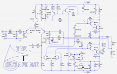
Following a request of The Prof, here is an example of Circlophone modified for current-drive.
Values are for 4Ω load nominal, if the impedance is different, R22 should be modified accordingly, although it is not strictly necessary, but then the input sensitivity will change.
Values are for 4Ω load nominal, if the impedance is different, R22 should be modified accordingly, although it is not strictly necessary, but then the input sensitivity will change.
Attachments
great, thank you!
I do not know the Prof, however the idea of current drive for dynamic speakers is valuable for me too.
Elvee, did you listen to the music switching the modes of your amp from VFA/CD?
Following a request of The Prof, here is an example of Circlophone modified for current-drive.
Values are for 4Ω load nominal, if the impedance is different, R22 should be modified accordingly, although it is not strictly necessary, but then the input sensitivity will change.
I do not know the Prof, however the idea of current drive for dynamic speakers is valuable for me too.
Elvee, did you listen to the music switching the modes of your amp from VFA/CD?
I do not know the Prof, however the idea of current drive for dynamic speakers is valuable for me too.
Elvee, did you listen to the music switching the modes of your amp from VFA/CD?
I did the opposite in fact 😀: I responded to The Prof's request, as it was asked politely, but I'am no great believer in CD, at least for speakers that aren't specifically designed with this mode mind.
Today's speakers are designed for a source impedance ~=0, and if you present them with an infinite impedance, they'll have a weird behavior at some frequencies.
The subjective effect might be pleasant, but that's a totally different subject.
What I did was to cancel the copper resistance of the drivers by presenting a negative resistance based on a thermal image of the voice coil.
This more or less equates to an implicit MFB, provided the driver+speaker combo is not averse to that kind of operation.
The results were somewhat disappointing: there seemed to be some improvements, but certainly not on the scale I had hoped for.
That said, I didn't invest lots of resources, be they time, thoughts, acoustic optimization, financial means, etc.
The subject probably deserves more in-depth investigation than I was prepared to allow, but I think this path is more promising than the CD
Current drive
I just thought it could be useful to illustrate into which cabinet the tone parts go.
Five elements of current drive that do belong in the amplifier enclosure: A goodly working input circuit (there are resistors series to the signal there and that's also current drive), Base Stoppers (current drive for transistors), A modicum of power filtering on the amplifier board at the very spot where the dc umbilical cable contacts the amplifier board (even the tiny loss of the filter is also current drive), power supply capacity sized to exactly support the expected speaker (the taper is current drive), and either parallel bjt's (with ballast) or fets at the output (the ballast is current drive).
Other efforts belong inside the speaker cabinet, not in with the amplifier. Fancy a BSC? I sure do. It doesn't belong in the amplifier cabinet. 😀
Question:
If anyone has a Circlophone hooked up to a scope or other measuring equipment, could you tell me the effect of adding just one part at a specified locale?
The locale is the very spot where the dc umbilical cable joins the amplifier board.
The part to add is 1 (one) capacitor, connected from V+ to V- (no tap to 0v), and to the specs of: polyester (100v or higher) or electrolytic (if polar then 250v or higher, with an ordinary "power cap" type such as Mallory SEK or similar ordinary cap), that cap within a range of 2.2uF to 4.7uF.
Sorry that I don't know the perfect capacitance value; however the applicable range is not very big. Yes, the voltage range suggested for a polar electrolytic is ostentatiously high on appearance, but there is a purpose: I would like to test with only a cap and not a somewhat zener acting cap, which (the latter) could happen if the voltage tolerance is too small (250v spec will suffice for the polar electrolytic if used in this peculiar add-on).
It could make the amp run cooler, and/or pointlessly run more stable, and/or decrease distortion, and/or sound more pleasant with no measure to explain it, and/or do absolutely nothing whatsoever.
Then the rest of the question is this: Was the difference worth 6 cents (and board space) to do it?
I'm sure that (above) addition won't harm a circlophone.
P.S.
The question re-phrased a really different way involves adding capacitance (value range not determined--possibly a range of 22u~270u, and try smallest firstly) loading the output of D4 and D5 (part numbers refer to original schematic, post#1). I don't know what would happen with that alternative, so there is a chance of harm with that alternative, because I just don't know. What I do know is that power for the speaker comes through those schottky diodes and that robbing the speaker of power for errata from the amp involves loading the diodes with caps; and since the harmonic signature is 7khz, then a big cap isn't needed.
Alternatively, connecting the output of D4 and D5 with 1 (one) 250v cap in the range of 2u2~47u is possibly a good experiment, if it doesn't happen to cause smoke. Sorry that I can't pinpoint the exact value or guarantee what might happen, if the part is added.
It could explode, do nothing useful, or it could suppress the harmonic signature by up to 80db. I don't know which of those will actually happen.
A cap connecting the emitters of Q12 and Q7 would almost certainly have disastrous consequences, so best to simulate that first.
A cap from V+ to V- at D4 and D5 would be bypassed through C9 and C8. If the new cap is film it could resonate with the existing bypass and that could cause problems, so I suggest a 10uF+ film cap - large enough not to resonate - or use a lytic.
A cap from V+ to V- at D4 and D5 would be bypassed through C9 and C8. If the new cap is film it could resonate with the existing bypass and that could cause problems, so I suggest a 10uF+ film cap - large enough not to resonate - or use a lytic.
- Home
- Amplifiers
- Solid State
- ♫♪ My little cheap Circlophone© ♫♪