I read some where that gate resistors reduce oscillations in MOSFET's during conduction at some stage, but I am not sure. I also request Mr Elvee to please check the effects of these resistors in simulation.
Oscillations are due to the interaction of the device and circuit parasitics as reactive elements, notably inductance of pcb traces, but also coupling between traces. It is extremely dependent on layout, so it is not possible to study it in a simulator without also modeling the PCB.
Elvee also made the CircloMOS 😉
But it is a different circuit shared before Circlophone.
It's cheap, it's N, it's dirty, it's.... The CIRCLOMOS!!!
Yes, the CircloMos is a war machine, quite different from the Circlophone, but it can work for audio.
Gate stoppers are an easy solution, but they are best avoided whenever possible: they introduce parasitic poles in the global response, eroding the phase margin.
If the MOSFets are wired to a remote sink rather than directly on the PCB, they might be unavoidable, but in this case, ferrite beads are preferable, as their influence on the GNFB is smaller at frequencies of interest
Mr terranigma,
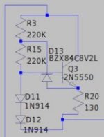
If I implement your designed CCS circuit in place of R21, how much current it will maintain and the voltage range in which it will maintain constant current. I have designed a layout which will house this circuit and can be replaced in place of R21 as a small vertical pcb module.
If I implement your designed CCS circuit in place of R21, how much current it will maintain and the voltage range in which it will maintain constant current. I have designed a layout which will house this circuit and can be replaced in place of R21 as a small vertical pcb module.
Mr terranigma your CCS circuit.
It is not my design. It is just one of Elvee's countless contributions. Take a look at post #1438. 1-1.5mA is the current that CCS or R21 have to provide.
Bear in mind that if you are going for 50V rails, you'll need proper heatsink in order to radiate the heat at idle. General opinion regarding mosfets is that they get better with heat but this doesn't mean improper cooling.
Yes, the CircloMos is a war machine, quite different from the Circlophone, but it can work for audio.t
Nice to hear that. I can appear on that thread anytime soon asking bizarre questions.
Last edited:
Mr Elvee,
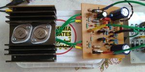
Today I tested Circlophone with very old IRF350 metal case MOSFET purchased in the year 1985. Surprisingly this circuit is also accepting those MOSFET's not specifically made for audio circuits. This is a switching MOSFET with high input capacitance of 3000pf. I therefore pretend that any high power MOSFET not specifically made for audio may be substituted in the circuit.
The heat dissipation is high and need bigger heat sink. The amplifier has been power on for more than 12 hours without any failure.
Attachments
Mr Elvee,
On voltage measurement, I have found that there is mismatch in GS voltage of both MOSFET at steady state with no signal. The MOSFET on the negative rail side measures 3.70V while that on the positive rail measures 3.5V. What could be the cause of this mismatch?. The voltage across 1 ohm resistor on negative side measure 185mV.
With this setup I didnot find any distortion and steady state operation is stable. I think I will need a bigger heat sink as this heats up quite high. VAS transistors heating is normal.
Thanks
MOSFets have a large dispersion on the threshold voltage; 0.2V is nothing.
If you want better, you need to select them, but a deviation of 0.2/3.5=5.7% is easily swallowed by the C topology.
185mA quiescent current is bang on target: no need to change anything
If you want better, you need to select them, but a deviation of 0.2/3.5=5.7% is easily swallowed by the C topology.
185mA quiescent current is bang on target: no need to change anything
Mr Elvee Thanks, for the reply. That means GS voltage will vary with Gate-Source Threshold Voltage of each MOSFET. I have further two more questions:
1. Since R8 & R11 are current sensing resistors, what type of composition would you prefer. Carbon, Metal, Metal Oxide or Wire wound.
2. I would request you to please refer to Post # 1850 of Mr Terranigma where in he has actually shown square wave pattern with and with out R18 and C12. He has found out that without R18 and C12 the square wave is smooth. In yout MOSFET version simulation you have used them. What is your recommendation.
Thanks
Since the dissipation in R8 and R11 will typically be lower than 0.25W, you are free to use any type, but WW resistors being inductive, they might have small parasitic effects therefore I recommend any other type. Accuracy is not critical, and plain carbon types are perfectly OK, as are metal and MOX, of course.
The reality always wins against simulation, and I have not built the MOS version, unlike Terra, therefore I suggest you follow the path he laid.
It is understandable: MOSFets have a large input capacitance, and the GS resistor is larger than the BE one of the BJT, meaning they mostly self-compensate
I have read in earlier posts that there is difference in sonic quality in BJT and HEXFET version of Circlophone. I have made both BJT and MOSFET versions of Circlophone with in a short span of time with same power rails voltage and have found almost no distinguishable difference in sonic quality. I think it may be due to VAS transistors which are video grade transistors used in high definition colour TV as video drivers. One is C2621 from Sanyo and other one is BF870 from Philips.
That's how things should be: you have achieved ~perfection in both your builds, and perfect is indistinguishable from perfect, even if it is attained through different means.I have made both BJT and MOSFET versions of Circlophone with in a short span of time with same power rails voltage and have found almost no distinguishable difference in sonic quality.
Bravo!
Elvee,
I came across some mosfets produced by Analog Power in TO220 case. Their specs look spot on except very poor DC SOA. Can you take a look at the attached datasheet please? Their 300W Pd spec seems make sense only in very fast switching power supplies. Are such mosfets suitable for audio as output devices, particularly Circlophone? I suspect that they will blow very badly on low frequency audio signals at moderate listening levels.
Thanks.
Attachments
Unfortunately, they are representative of the new MOSFets generation: phenomenal specs, and microscopic SOA, totally unusable for linear applications.
The specs themselves are poorly written and misleading: the 300W rating comes with a footnote: 1” x 1” FR4 Board, which is of course totally impossible.
The correct note appears later: Pulse test: PW <= 300us duty cycle <= 2%.
Of course, with a Rth j-c of 1°C/W, 300W is downright impossible.
At 20V Vds, they tolerate just under 100mA: you could fry them in just a headphone amplifier. You'd be better with a IRF510
@ Katiyar
Sorry for being late in my congratulations on your CIRCLOMOS build, which I saw only now!
I am more than happy about one thing--that you have been able to achieve something that many set out to do, viz. building an amp without an audible "signature"!!
I am right behind Elvee in my accolades to you on this significant achievement.
I suggest you do a series of listening tests with both topologies as soon as you finalize the builds and update us.
Cheers!
Mr terranigma, You have used 8.2V Zener in CCS of Hexfet Circlofone. Is it that you have simulated with 65V Rail. Earlier CCS simulation circuit use 6.2V Zener for lower Rail Voltage. What value should I use for 24-32V Rail Voltage. Thanks
Mr terranigma, You have used 8.2V Zener in CCS of Hexfet Circlofone. Is it that you have simulated with 65V Rail. Earlier CCS simulation circuit use 6.2V Zener for lower Rail Voltage. What value should I use for 24-32V Rail Voltage. Thanks
According to simulation, CCS provides 1.25mA with 8.2V zener, 1.0mA with 6.2V zener at 30V rails. So, both zeners are suitable even though 6.2V provides nominal current, I would use 8.2V zener anyway. 1-1.5mA is ok.
Mr Prasi,
Did you get your PCB from "Smart Prototyping" firm. Please share your experience and total cost incurred including customs involved. Thanks
Did you get your PCB from "Smart Prototyping" firm. Please share your experience and total cost incurred including customs involved. Thanks
Hello Mr. Katiyar,
I am yet to receive pcb from them. they are shipped and tracked too. they are a bit slow, almost take 8 days to manufacture and then 2-3 days more for shipping update.
Due to covid and on-going issues, shipment from china is very slow by Chinese post. Same case with pcbway too. I am yet to receive apex fh-100 xrk mod pcbs which were ordered from pcbway much much before the circlophone pcbs.
I will share photographs of pcb once they are here.
regards
prasi
- Home
- Amplifiers
- Solid State
- ♫♪ My little cheap Circlophone© ♫♪