>2SK3549, 2SK3678, 2SK3533, 2SK3875
Aren't they obsolete? Mouser doesn't carry them...
IRF640 is nice for light power...
Probably they will not available on Western suppliers. I think that they are out of scope of counterfeit business so I plan to acquire them from Eastern market with very reasonable prices.
IRF640 has same input capacitance as IRFP240, so 240 will be the much better choice. If you don't want to deal with obsolete parts, you can consider Fairchild ones such as FQA28N15 (higher power, lower capacitance) . F5 thread is a good source for getting info about these ones.
Mr terranigma, Specific reason of choosing TFZ series zener diodes in Hexfet simulation. These are not recommended for new designs and not available in India. Other substitutes. Can I try protype as per schematic used in simulation.
Thanks
Thanks
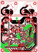
I have tried to get the layout of the board modified from BJT to HEXFET as per simulation schematic. I am not very sure for its correctness. Layout is attached.
I have myself found at least two mistakes in the layout:
1. Orientation of Q7 & Q8 to be reversed as per pin layout of 2N5401 transistor
2. Transistor numbers of Q9 & Q10 to be interchanged.
There could be other mistakes as well in the layout.
1. Orientation of Q7 & Q8 to be reversed as per pin layout of 2N5401 transistor
2. Transistor numbers of Q9 & Q10 to be interchanged.
There could be other mistakes as well in the layout.
Mr terranigma, Specific reason of choosing TFZ series zener diodes in Hexfet simulation. These are not recommended for new designs and not available in India. Other substitutes. Can I try protype as per schematic used in simulation.
Thanks
No specific reason. I just pick them from Ltspice diode list by looking their voltage values. Any non-faulty zener will work. If you wanto to use a single zener, its value must be around +Vs and power dissipation must be minimum 1/2 watt.
I have tried to get the layout of the board modified from BJT to HEXFET as per simulation schematic. I am not very sure for its correctness. Layout is attached.
It seems you flipped the original layout according to the rails. This is rather a cosmetic change except you don't feel right when negative rail is at upper or left side. This flip may cause wrong polarity and wrong orientation issues on silkscreen (as you mentioned on last post). Thus you have to strictly check active part orientations.
Other thing that I have to notice is unnecessary gap fillings. I would avoid filling those blank spaces which I think highly counter productive. I don't see any benefit of them either. You can move parts a bit upper and relax the layout since there is no driver transistors anymore.
You can check-out Bagla H's pcb at post#1810 . It is double layer but very well done in my opinion.
Attachments
Thanks for suggestion.
I forgot to mention:
When you use TO3 transistors, you should consider good fitting of "L" shape angle heatsink attached top of the PCB. Your layout is suitable for such use but those wire jumpers prevents proper fitting of the heatsink.
I suggest you to avoid those wire jumpers and build two versions separately. I think that there is no practical benefit of the modular design here but contrary.
If you really intend to make a single modular design you may start from avoiding those wire jumpers first. It is easy for Drain and Source pins by directly making a via between them at bottom. For Gate, you can use a small wire jumper or another via at bottom.
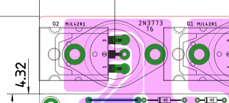
Even the pads of to-3 can be used with some imagination to fit to-247/264
Very clever. I wish that I have tried it when I was doing my own layout here.
NOTE: Placement of 10K input impedance resistor is wrong on that (my) layout. When I look at it now I see that it can be improved at many sides.
Last edited:
Mr Terranigma very good suggestion by you and Mr Prasi. My idea of using TO3 MOSFET was to use IRF350 which I have used earlier in some other circuit. TO3 MOSFET are not easily available and very expensive. Any way I will try to improve further as to how Jumpers can be avoided.
Mr terranigma, Can you suggest suitable value for R7 & R14 resistors for a lower supply voltage of 32-0-32 V DC supply. I have also noticed that no gate resistors have been used for Mosfet. Also have you physically tested this circuit because as per simulation results it seem excellent transformation from BJT to HEXFET. I am seriously interested to build Circlophone as per this schematic. I am also modifying PCB layout as per your suggestions. I shall be thankful for the reply.
Mr terranigma, Can you suggest suitable value for R7 & R14 resistors for a lower supply voltage of 32-0-32 V DC supply. I have also noticed that no gate resistors have been used for Mosfet. Also have you physically tested this circuit because as per simulation results it seem excellent transformation from BJT to HEXFET. I am seriously interested to build Circlophone as per this schematic. I am also modifying PCB layout as per your suggestions. I shall be thankful for the reply.
R7 and R19's value proposed by Elvee as 390 ohms. When I simulated effects of the this resistor's value on performance, I see that higher value decreases THD but slew rate affected negatively. I think 390 ohms is the optimum value regardless the supply voltage. First mosfet version shared by Elvee at post #62
Bear in mind that mosfet amps slay the rail voltage by the value of the gate threshold voltage. You will see less amplitude at output comparing to the BJT version. For 32V rails, expect about max +/-27V swing at outputs. Gate threshold value varies by the manufacturer and the model.
I actually built that circuit with different small signal transistors (BC550C, 2SA992 etc.) and 2SA1370 as bias servo (Q5, Q6). You can use your preference of the transistors (and mosfets of course) as long as their specs meet the requirements. I'm using my setup for a couple weeks without a proper casing. I already shared its photo at post #1862 and #1850.
Last edited:
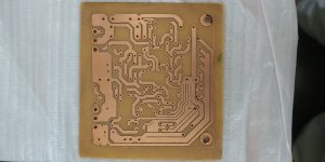
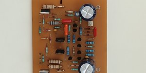
I have modified the Circlophone BJT board to HEXFET as per simulated schematic. I will assemble the circuit on this paper phenolic board. I intend to use following components:
Power Mosfet: IRFP240 / IRF350
VAS : BF470
Supply Transformer 24-0-24 V AC.
Picture of etched board attached.
Power Mosfet: IRFP240 / IRF350
VAS : BF470
Supply Transformer 24-0-24 V AC.
Picture of etched board attached.
Attachments
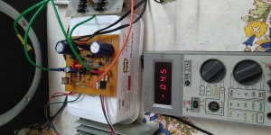
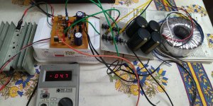
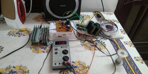
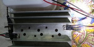
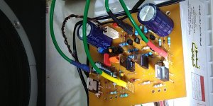
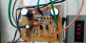
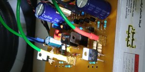
Wow, what a conversion from BJT to MOSFET version. I assembled the prototype today and was astonished with the performance. You are really a genius. Output offset is only -4 to 5 mV. No noise, no oscillations and no motorboating. The build is as follows:
Supply Voltage 24-0-24 V AC Toroidal with 30,000MFD capacitor bank.
1. BC 546 - CDIL India
2. 2N5401 - KEC
2. VAS BF870 (4.7 pf not used since I did not have with me)
3. BAT 54 Schottky - SMD under the board
4. MOSFET - IRF540 (Harris) purchased about 30 year back
4. MBR745 - Taiwan Semiconductors
5. Capacitors Polyster - Philips
6. Zener - 15V + 15V
7. R21- 47K
The only change from your circuit is addition of 220R gate resistors. Since I do not have scope, I cannot see the behaviourial change by this inclusion. I think it stops oscillation in the MOSFET at some stage during conduction.
Photographs are attached.
Thanks again
Katiyar
Attachments
-
 IMG_20210623_125545_BEAUTY.jpg563.5 KB · Views: 336
 -
 IMG_20210623_125616_BEAUTY.jpg650.2 KB · Views: 327
 -
 IMG_20210623_125535_BEAUTY.jpg612.5 KB · Views: 301
 -
 IMG_20210623_125925_BEAUTY.jpg449.2 KB · Views: 293
 -
 IMG_20210623_130621_BEAUTY.jpg421.7 KB · Views: 179
 -
 IMG_20210623_125555_BEAUTY.jpg443.9 KB · Views: 171
 -
 IMG_20210623_130631_BEAUTY.jpg960 KB · Views: 183
 -
 IMG_20210623_120905_BEAUTY.jpg639.5 KB · Views: 199
The only change from your circuit is addition of 220R gate resistors. Since I do not have scope, I cannot see the behaviourial change by this inclusion. I think it stops oscillation in the MOSFET at some stage during conduction.
Nice build. I think you're the second one after me who built and shared a MOSFET Circlophone in this thread. I don't remember any discussion regarding gate resistors here. I highly suspect that they needed in Circlophone and I suggest that build other channel without them in order to observing any counter effect. Elvee would say best if they are safe or not.
EDIT: I forgot that Bangla H actually built and shared mosfet version too. So you are third at best.
Last edited:
As far as I remember, Elvee mentioned in one of the posts, that gate stoppers were not needed for Circlophone.
Thanks Mr Minek123 and Mr Terranigma,
The sonic clarity of This build is just similar to my first BJT build with 2N3055 as output transistors. Crystal clear sound with no distortion and dead silent with input short condition. The original pcb layout was developed by "Project16". I have tried to modify this layout to relocate the placement of available components and to avoid any possible earth loop which may cause instability and noise. Incidently the output offset voltage of both builds are within +/- 5mV.
I read some where that gate resistors reduce oscillations in MOSFET's during conduction at some stage, but I am not sure. I also request Mr Elvee to please check the effects of these resistors in simulation.
Any way I am extremely happy with this build and encouraged to make another build with higher voltage (+/- 50V DC) and IRFP240 MOSFET's.
Thanks
- Home
- Amplifiers
- Solid State
- ♫♪ My little cheap Circlophone© ♫♪