If you short the diode pack out it removes the bias voltage and forces a zero bias condition in the output stage. The amp still works normally but with a little more distortion (crossover distortion). Forcing zero bias current an added safety for the output transistors.
As long as you are using a bulb tester you should be OK if you don't that.
As long as you are using a bulb tester you should be OK if you don't that.
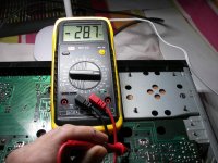
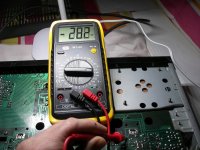
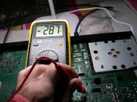
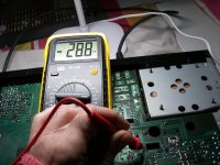
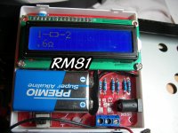
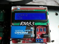
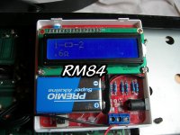
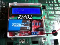
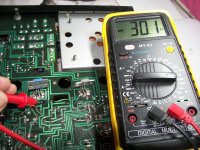
OK. Checking DC on the four 0,33 resistors, with Dm5 and DmM6 shorted, with safety bulb to power up.
One channel ok (close to zero) but the other channel too high: -28,7 V. in each leg of R81 and R83.
One channel ok (close to zero) but the other channel too high: -28,7 V. in each leg of R81 and R83.
Attachments
So this seems to show the PNP output is possibly defective. We know you had zero volts on the 0.33 ohm with them both removed.
One more thing to check first. Switch off and make sure that Rm79 and Rm77 are OK (both 330 ohm). If they are then remove the PNP output and check it on a meter for leakage.
One more thing to check first. Switch off and make sure that Rm79 and Rm77 are OK (both 330 ohm). If they are then remove the PNP output and check it on a meter for leakage.
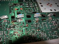
Sorry for the thread diversion: happy to see one more example of an amp built on Phenolic boards, single face, through hole components.
I still use that, am somewhat despised by my Boutique Guitar Amp colleagues here in Argentina (who order everything from JLC PCB, often even populated boards) but they work fine, like always.
If anybody doubts, I point at excellent amps such as yours 😉
Only precaution: be very careful when removing parts, it´s easier to pull pads and tracks in Phenolic than in Epoxy, do not wiggle parts but clean out solder well, use a solder wick as a final "cleaner".

Please short your component tester probes/crocodile clips; what does screen show?4x0,33ΩK resistors. Main fuses of power supply OK.
Resistors are nominal 0.33 ohm but screen shows 0.6V so I suspect it is also showing wire/connector residual resistance, I want to know that residual value which must be substracted from displayed/screen value.
To avoid typing full description every time I´ll call it PrT (Parts Tester) unless you have a better (short) name.
Sorry Mooly, I´d call that short or short across or short end to end bias diode pack, otherwise it´s somewhat confusing.Link out the series diode pack
There is also another diode pack at the main supply.
No,not OK at all.Dm5/Dm6. Seems to be OK.
1) there is a significant difference between 1.93V forward diode drop (Vf) and 1.21V Vf, a full diode drop is missing.
WHY?
As a side parameter, one diode pack shows 177pF ; the other confuses the PrT , WHY?
"WHY" means I found something worrying, whose origin/motive must be found.
2) you are measuring "in circuit", so there are other external elements in parallel.
Most notably: driver and power transistor BE junctions, which are all in series, in parallel with Bias diodes, and amount to "four diodes".
IF we are "missing one", probably ONE B-E junction (Base Emitter) is shorted, meaning one transistor of four is shorted.
Which one?
It remains to be determined.
PS: can somebody post the full schematic or at least power amp and supply?
I bet other Forum members would participate if so.
What power is your bulb?Power up with a bulb tester.
to be continued ...
Last edited:
Since edit time has expired, new message.
Maybe said time can be reactivated or extended so I can keep adding new findings as I read the thread.
It would be nice also to have an edited message travel automatically to the end of the queue,after all it contains new data.
A suggestion for Jason?
back to the problem:
the PrT shows 3 resistors as 0.6 ohm, but one as 0.3 ohm WHY?
to be continued
Maybe said time can be reactivated or extended so I can keep adding new findings as I read the thread.
It would be nice also to have an edited message travel automatically to the end of the queue,after all it contains new data.
A suggestion for Jason?
back to the problem:
the PrT shows 3 resistors as 0.6 ohm, but one as 0.3 ohm WHY?
Gracias tocayo 😉Service manual.
to be continued
again time limit 💩
1) please call them like in the schematic, Qm and not plain Q , it is confusing.
2) please measure the +V rail, I suspect it´s around +35.9V
So +35.9V at Qm26 is the +V vrail.
No voltage drop across RLm1 coil because Q26 is not passing current. WHY?
Too sleepy to go on, 5 AM here, good night/morning.
PS: you did not answer Bulb wattage and a couple other questions: they are IMPORTANT.
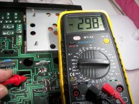
Too much DC voltage on collector Q26 = 35,9V.
1) please call them like in the schematic, Qm and not plain Q , it is confusing.
2) please measure the +V rail, I suspect it´s around +35.9V
So +35.9V at Qm26 is the +V vrail.
No voltage drop across RLm1 coil because Q26 is not passing current. WHY?
Too sleepy to go on, 5 AM here, good night/morning.
PS: you did not answer Bulb wattage and a couple other questions: they are IMPORTANT.
Too much DC voltage on collector Q26 = 35,9V.
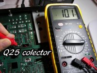
Q25 DC colector = 10,1V.
Don't worry over those. They are incorrect because of the high DC offset.
This measures of DC are with all output NEC removed, with Dm5 and DmM6 shorted.
Go back to the first tests we did. The voltage on the 0.33 ohm resistors was zero and the resistors seem OK

You then fit the output transistors and the offset voltage is a very high negative value on one channel. This suggests the PNP output transistor is conducting and pulling the output negative. That would happen if was leaky or if there was enough voltage across the 330 that goes between base and the main output line. Excess voltage across the 330 ohm is unlikely given that the DC offset is zero with the output pair removed. You should still check it though.
If you are not sure then make a note which is the 'good' channel, then remove the output transistors again and confirm the DC offset really is zero on both channels. Get it back to that state. Keep the output transistors from the 'good' channel separate so you know which they are.
Now check the voltage across the 330 ohm resistors. Should be almost zero. If it is then I think one of the output transistors is faulty (the PNP one).
Now fit the output transistors from the good channel to the bad one. That channel should now work with no offset.
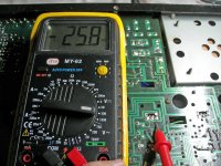
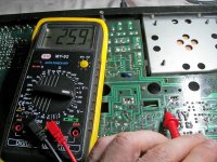
All 4x0,33 resistors are OK. New measure. Dm5 and DmM6 shorted and all outupt transistor mounted. One channel ok (near 0V on collectors) but the other channel with –DC voltaje on both collectors. All transistor are cold, an relais still dead.
Attachments

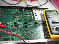
The collectors go to the supply rails and these should always have supply voltage on them. Do you mean the emitters? The emitters are the leads that go to the 0.33 ohm resistors. They should have zero volts on them.

I meant Emitters (0,33 resistors leg). The relay protection circuit does’t work, I think output transistors are not the problem. With the short I made on the speaker terminals maybe some component burned or smoked.
Listen 🙂 you must be logical in this.
We have proved you have no DC offset when the output transistors are removed. Yes? We did that test and you showed zero volts on the 0.33 ohm resistors.
When you refit the transistors it is back to a high negative DC offset. Yes? That is what we tested next.
Conclusion, the most obvious suspect is the PNP output transistor. Forget what that component tester says, prove the theory by substituting that transistor.
The relay protection is working if the relay does not close with a high negative offset present. It is doing what it should.
OK, so that is now different to what we had in post #17:
https://www.diyaudio.com/community/threads/my-ka-5700-has-burned-out.378199/post-6892465
It's no problem but we need to go back to the basics again now 🙂
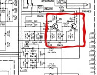
Leaving the transistors out of circuit can you place the black meter lead on the junction of the 0.33 ohm resistors and then measure the voltage at these points I have labelled 1, 2, 3 and 4.
Record the results and post them here.

https://www.diyaudio.com/community/threads/my-ka-5700-has-burned-out.378199/post-6892465
It's no problem but we need to go back to the basics again now 🙂
Leaving the transistors out of circuit can you place the black meter lead on the junction of the 0.33 ohm resistors and then measure the voltage at these points I have labelled 1, 2, 3 and 4.
Record the results and post them here.
- Home
- Amplifiers
- Solid State
- MY KA-5700 has burned out