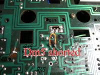
First standout from those is that Qm19 must be open circuit. You have -11v across the B-E junction with the emitter the most positive. That shows the B-E junction is open.
Also 3 and 4 should be very similar (whatever they might be) if Dm5 is linked out. Look at the circuit, You have Rm93 and Rm55 in parallel which is like a single 16 ohm resistor.
So points 3 and 4 should be almost the voltage. Or perhaps you have not got Dm5 linked out 🙂
Qm19 is definitely open circuit with -11v across the B-E junction.
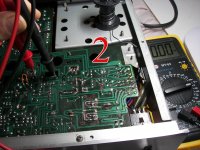
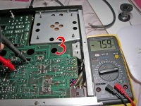
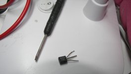
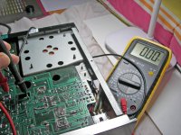
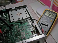
New measures with a new Q19:
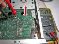
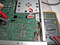
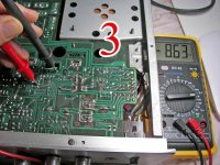
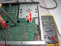
1) 0,13
2) -0,07
3) 0,17
4) 0,01
Dm5 linked out. Relay working. I can't mount the output transistors yet, I am waiting for a new thermal paste (Aliexpress).
1) 0,13
2) -0,07
3) 0,17
4) 0,01
Dm5 linked out. Relay working. I can't mount the output transistors yet, I am waiting for a new thermal paste (Aliexpress).
PLEASE be consistent with picture names.
1) it´s ridiculous-nonsense to use LOOOOOOONNNNNGGGGGG meaningless names such as 111111111111111111111.jpg , which makes it impossible to quote them for reference.
2) GIVE EACH IMAGE ITS OWN NAME, such as (starting from Day 1, the original post) : Img-001 , then Img-002 and so on, by chronological order.
Currently you have a dozen 11111111111111111111.jpg , ALL DIFFERENT, a dozen 22222222222222222222.jpg , etc.
Thanks.
PS: maybe you can ask and get permission for a, say, 1 hour "window" (or 6 hours) so you can edit all those picture names into something usable, quotable, searchable.
As is ..... 🙄
PS: amigo!!! no te enojes! 🙂 , es por tu bien 🙂
So its looking good so far 🙂
When you refit the output transistors and test it again you must keep the bulb tester in place. Make sure the amp is OK keeping the diode pack shorted.
If all seems OK then remove the short on one channel at a time and test again this time checking that bias current is correct.

When you refit the output transistors and test it again you must keep the bulb tester in place. Make sure the amp is OK keeping the diode pack shorted.
If all seems OK then remove the short on one channel at a time and test again this time checking that bias current is correct.
No big deal , just to keep images easier to quote in answers 🙂I apologize for that, it will not happen again. Happy New Year!
Happy New Year to you.
Ps: do they still eat 12 grapes on Christmas Eve and New Year dinner for good luck or it´s a lost custom?
Some of us of Spanish stock still do it around here.
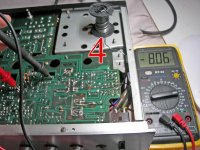
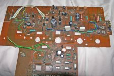
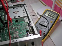
Last measurements with output transistors on board and diode pack shorted:
1): 0,06 V
2): 0,00 V
3): 0,83 V
4): 0,65 V
All seems to be OK. I think bias current are the same, customised/adjusted by Sakis ten years ago.
1): 0,06 V
2): 0,00 V
3): 0,83 V
4): 0,65 V
All seems to be OK. I think bias current are the same, customised/adjusted by Sakis ten years ago.
Attachments

So all good so far. You now need to try it with the diode pack back in circuit and I would advise you use the bulb tester initially. Follow the procedure given in the manual to check it is OK:
https://www.diyaudio.com/community/threads/my-ka-5700-has-burned-out.378199/post-6895353
https://www.diyaudio.com/community/threads/my-ka-5700-has-burned-out.378199/post-6895353
All OK. Tested with music and speakers, it sounds great. I will use it to listen TV through a DAC and a couple of a cheap Infinity Primus, as a main amplifier I have a Marantz PM8003 with a pair of Dynaudio Audience 62. Thank you very much Mooly and all DIY people. Greetings from Spain.

- Home
- Amplifiers
- Solid State
- MY KA-5700 has burned out