Hello! Thank you for your answer.Yes i also thought that TQWT may be an easier box for my application.Can i built it with double drivers? It is for only one driver though
Tapered Quarter Wave Tube
Tapered Quarter Wave Tube
Greets!
You're welcome!
Yes, two works in an inverse tapered TQWT, the opposite layout of the one you posted [vent opening/'terminus' at the narrow end with the driver offset from the closed wide end]. Plenty of this type has been built/documented, but now that I want a picture or drawing of one, Google can't seem to find one. 🙁
GM
Not that one. You need a 21st century design with driver offset. Like the B**e box you showed in post #1.
Last edited:
Seen alot of tapped Horns around these dimensions for 6inch driver, one with tagband comes to mind. Even google image search will show alot.
it is the same principle near enough.. I am not sure if the bandwidth is shorter with more spl? than a transmission line of the same dimention
it could be the out of band responce for a transmissionline is more user friendly than a tapped horn, however I would be interested in comparability of output v frequancy of the 2 designs
The Tangband 30Hz Tapped Horn – Volvotreter Homepage
Pin by kelemen laszlo on Hangfalak | Pinterest | Horn speakers, Loudspeaker and Diy speakers
TH-Micro - a 6,5" tapped horn
Baby Tapped Horns start - DIY Audio Projects - StereoNET
I am certain there was a 40hz design lying about somewhere.
aha!
The Tangband 38Hz Tapped Horn – Volvotreter Homepage
also I am sure I did see a design that uses 2 .. 6 inch drivers per cabinet.
thats all I found so far,
https://www.youtube.com/watch?v=036X4IRnOhQ
Last edited:
The classic end-loaded Bailey/Radford/IMF fold. Sims show that just putting the driver on the back gives sufficient driver offset to improve the lines performance (at least in the one we simmed)
dave
I am not sure if the bandwidth is shorter with more spl? than a transmission line of the same dimention
A tapped horn is inherently a band-pass design with limited bandwidth, a TL can be FR (depending on driver).
dave
does the tapped horn output significantly more within its bandwidth? they are both essentially 1/4 designs.
Greets!
You're welcome!
Yes, two works in an inverse tapered TQWT, the opposite layout of the one you posted [vent opening/'terminus' at the narrow end with the driver offset from the closed wide end]. Plenty of this type has been built/documented, but now that I want a picture or drawing of one, Google can't seem to find one. 🙁
GM
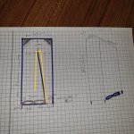
Hi.What about this one?I have just drawn it.
Attachments

I suspect that the drivers are not intended to be end loaded — you have missed the driver offset. The deflectors in the bend are actually counterproductive.
dave
dave
Dave, got a section view of one like this folded in half? MJK had one in his first? TL doc, but can't find it online anymore:
http://www.quarter-wave.com/Gallery/Mathieu.jpg
TIA,
GM
http://www.quarter-wave.com/Gallery/Mathieu.jpg
TIA,
GM
The picture is kinda low key, a tapered TL with the small terminus at the bottom (and the box attached to a corner)?
dave
dave

Hi.What about this one?I have just drawn it.
I like it. So long as the box has relevent space to breathe air down there with both those drivers and the vent.
p.s: why is driver offset relevant if it is for a sub? AH I recall, Means offset along the path of the line for better response and less pronounced resoundent peeks and things
means you need to find a design whereby some path length or box volume exists before the mainline of things

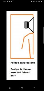
from what I recall, Its basically something like this. or similar.
not what the effect would be having it positioned like that though with the drivers where the fold is. I know it should see it all as one line but looks abit offy. someone else will know better
have you began any simulations?
how about a 10 inch driver instead of 2 6 inch ones?
not what the effect would be having it positioned like that though with the drivers where the fold is. I know it should see it all as one line but looks abit offy. someone else will know better
have you began any simulations?
how about a 10 inch driver instead of 2 6 inch ones?
Attachments
Last edited:
You offset the driver to acoustically kill the 1st unwanted harmonic so you can get away with less stuffing and less supression of the wanted fundamental.
dave
dave
Like this but upside down?
Well, folded in half so in profile it's rectangular with an angled divider to provide the inverse taper with the vent at the floor.
GM
Like this version of the one i posted: http://p10hifi.net/TLS/downloads/PushPush-B139-foldTL-map-300609.pdf
dave
dave
That last plan also points out that if you have 2 drivers, you can gain. abig advantage by mounting them push-push.
dave
dave
- Status
- Not open for further replies.
- Home
- Loudspeakers
- Multi-Way
- My ideal TL tower subwoofer idea!