The mute transistors, in their OFF state, add parasitic (and non-linear, I might add) circuit elements to ground. These parasitic parameters form a voltage divider with the series resistor, and hence are very much affecting the signal, even though they are not directly in series along the signal path. An audio signal does not have to go <i>through</i> a device in order to be affected by it! These little beasts may look innocent, but try removing them, and hear the difference for yourself!
I suppose one can consider the power-supply control mod as not just a way to prevent transients in the absence of those mute transistors, but also as a way of keeping the DACs and opamps 'warmed up', if you believe that sort of thing will improve the sound when you first turn something on... I'm not personally convinced, but for the puny bit of power consumed by these devices in standby, it certainly can't hurt.
With respect to simply modifying the mute scheme, we are not dealing with a current ransient at power on/off. The transients which come out of the opamp are voltage transients, so as soon as you remove the series output resistance, there is nothing to attenuate the voltage before it arrives as a signal at the input to your preamp. When the BJTs are in their ON state, they form a very low impedance element in the voltage divider with the 470R resistor, and your preamp is spared the trauma of these transients.
In any case, I carefully selected all of the player mods for maximum reversibility. I kept all the removed parts, and didn't do anything destructive, so with a few simple changes, I can have the player back to it's stock configuration (not that I'd want to...). On the whole, these are such simple and easy mods, that I think the benefits far outweigh the almost non-existant downsides. If you're not so confident in your SMT skills that you could remove and replace devices without damaging them or the board, I recommend you have a peek at my SMD Rework section in the wiki for some hints and useful techniques. The $25 hot-air tool is invaluable for this sort of work.
Chad,
Thanks for the comments!
I realize that the transients are voltage... I'm not sure what I was thinking last night. I thought I had an epiphany, but if those transistors are doing what you're saying, I certainly don't want them in there.
Not that I don't beleive you, but could you explain how a transistor in the off state can add these "elements" to ground? I'd like to understand this more... (no, I don't have a life 😎 - I just daydream about building my own Aleph, outboard DAC and preamp ALL DAY LONG at work.... 😉
Time for me to stop attempting to make great circuit designs as a fresh EE grad - but I have learned so much from forums like this in the past couple years... a LOT more than I learned in the classroom!
Thanks in advance for any comments!
Thanks for the comments!
I realize that the transients are voltage... I'm not sure what I was thinking last night. I thought I had an epiphany, but if those transistors are doing what you're saying, I certainly don't want them in there.
Not that I don't beleive you, but could you explain how a transistor in the off state can add these "elements" to ground? I'd like to understand this more...
(no, I don't have a life 😎 - I just daydream about building my own Aleph, outboard DAC and preamp ALL DAY LONG at work.... 😉Time for me to stop attempting to make great circuit designs as a fresh EE grad - but I have learned so much from forums like this in the past couple years... a LOT more than I learned in the classroom!
Thanks in advance for any comments!
think about it. the BJT presents a non-linear impedance which is affected by the voltage across the device (in this case Vce). so imagine a voltage divider where the shunt resistor is varying with the signal. when the signal is very small, the impedance of the BJT is X, but when the signal is large it's Y. there is some function I = f(Vin), where I is the effective current thru the device. for a perfect resistor, f(Vin) is a simple linear function (I = V/R) but for a BJT it is not so simple. the result is modulation, specifically harmonic distortion.
Done... 🙂
Hi all!
I just finished making the mods to my Sony NC650V
I just wanted to modify the primary stereo main outputs. I put in an AD1820 opamp to replace the factory one. I removed the 47uF decoupling caps and removed the BJT muting transistors. I also bypassed all the internal wiring and tapped off to my own new RCA jacks that I placed on the rear of the chasis.
All in all, I'm very impressed so far. The bass resolution and detail has dramatically increased, and the high end seems much more neutral. The rash sound in the midrange is gone, likely due to the removal of the caps.
For reference, the diagram is wrong in the Sony manual. It took me a while to figure this out. IC202 is labeled ast the "front 5.1" audio amp. The front channel 5.1 opamp is actually IC203, which is labeled as the rear 5.1 outputs. And IC204 which is labeled as the center/woofer 5.1 is actually the rear 5.1 outputs. And IC206 which is labeled as "audio amp" (presumably the main L/R outs) is actually the center/subwoofer output for 5.1. I should have learned to double check the labels by tracing the wires PRIOR to the removal of parts on the PCB, but... as they say, hindsight is 20/20.
So, to be clear, the main L/R output opamp is actually IC202. I removed caps C247 and C248 and transistors Q214 and Q215. I also ran a "jumper" wire across where the two caps used to be so that the original L/R RCA jacks would work if I ever wanted to use them at a later time. I tapped off these "jumpers" to solder some 30awg magnet wire to be run to the new RCA jacks that I mounted to the rear of the case. I also tapped off the collector pads of the two transistors to run a solid signal ground connection wire to my new RCA jacks.
My logic for adding additional jacks was that it seemed to be the easiest way for me to get around removing additional resistors (R239 and R240 - the 470ohm resistors serving as current limiters to the original muting transistors) and also the resistors in series after the relay switch (R307-R310). I was also to bypass the relay switch by adding my own RCA jacks.
I didn't, unfortunately, get to tapping into the Ever11 power supplies for direct, constant power to the opamps. The next time I open it up, I'm going to attempt making this power supply mod (thanks to Chad [HifiZen] and Dorkus). I'm also planning to add some/replace some of the power supply caps at the opamp pads. I'm wondering if just using the 47uF caps that I removed before as decoupling caps might work. Perhaps a just grabbing a couple nice SMT 1.0uF tantalum caps from work might do the trick too. I'm sure they have a much lower ESR and would probably provide better bass resolution than the old decoupling caps. I just didn't have anything here that would serve this purpose well this weekend, so I was trying to think of some alternatives.
BTW, thanks Dorkus for the info on the muting transistors. It makes plenty of sense now that you point it out. I never put together the fact of varying impedance through the Vce points on my own, but it now rings a bell. Perhaps I'll go through my physics of transistors book during lunch tomorrow to try to get back in shape on all this stuff. I wish I would have had some more practical appliations experience with this stuff... even with all the lab time I had, I didn't always get the whole picture...
OK - well, thanks Dorkus and HifiZen for the notes on your mods - hopefully mine will be ambition for someone else as well.
sounds like you are well on your way with those mods, congrats. many people think tantalum caps stink, but i actually don't think the 1uF SMT's by the ICs are a bad idea. try it out, and if it sounds stinky you can always take them out.
getting practical circuit experience in school is tough, even w/labs. i bet half the EE grads at my school would have no idea how to reverse-engineer something so simple as the muting circuit in the player. of course, those grads probably went on to careers in IT consulting or I-banking anyway.
hopefully in the mod project thread we'll make some progress w/a clock upgrade (Blair is hard at work on his 500V, to the point where he fried his PLL chip and is waiting for it to be fixed). i suspect a good clock upgrade will be the next big step up in sound quality, along with further power supply mods.
dorkus said:i'm currently hacking up my Sony NS500V DVD/SACD player.
------------------------------------------------
Dorkus
Can you please summarise what you finally did to the clock? I am about to do it to a SCD670 with a similar citcuit.
Fred
Thanks to all who helped me replace the op amps in my NC 650V, including Tieftoener, Dorkus and Hifizen (for his Wiki on smd re-work).
The player sounds wonderful with the AD8620's in all 6 channels, plus the main L/R.
Catrafter
The player sounds wonderful with the AD8620's in all 6 channels, plus the main L/R.
Catrafter
SACD and PCM
"Regarding output in PCM format, one of my main reasons is that I want to be able to perform signal processing on the data, which is virtually impossible with DSD streams. In fact, I learned something interesting today while reading some online articles... it seems DSD studio equipment actually employs a quasi-PCM format for editing(!)... it would seem that all the marketing hype about maintaining the purity of the data streams by avoiding PCM conversions is just propoganda! It is well known that in order to do any useful studio editing, some form of PCM conversion is almost essential, and of course it turns out that this is pretty much exactly what happens during the process of producing a master."
Regarding this post. I am a Assistant producer. I've had a chance to work on a few DSD SACD remasters from the origonal anologue sources, and one new recording. the new one was origonally done in PCM format in protools and remixed for SACD purley for the 5.1 effect. The producer I worked with was very old school anologue and takes allot of pride in his work and I can assure you there was no quasi PCM involved. You should see the equipment required for this opperation! it is very impressive. Most mixing opperations such as gatting compression ans so onwere done in the anologue domain. DSD is not such a new technology. TELARC digital was the competing format for the new digital recording geer in studios and was I believe 18bit 50khz DSD wich was eventually beat out by PCM. You will notice Telarc has released many off these recordings in SACD format upsampled to 192/24 although notpure 192/24 at least it stays true to DSD format.
Late to the party! My DVP-NS500V Mod!
So, I've had my DVP-NS500V for years; bought new. It's been used sparingly, most recently as solely a DVD player for my young daughter. But, I've been itching to tinker with it, and when I decided to give it a go, I found this thread, which was tremendously helpful.
Most of my CD/DVD player mods simply bypass the output stage through .5-1 uf capacitors to newly installed, gold-plated RCAs. However, for this one, I was really intrigued with the idea of the more complex mod of replacing the op amp. And, I had a few SMD Burr Brown OPA2134's lying around, so what the heck!
I was a bit worried, however, as I've never had good luck removing/installing SMD ICs, likely because I don't have the right tools, and I'm usually impatient. But, I was determined this time to do it right.
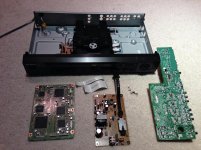
I started by completely breaking down the unit, and removing all the boards (not that it was necessary, I just wanted to get a look at everything). The bulk of the work would be done on the audio board, and here was my 7-step plan:
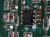
1) remove the opamp driving stereo output (I decided to leave the 5.1 output as stock)
2) remove the stereo RCAs (which also meant removing the composite video, but oh well)
3) install Burr Brown OPA2134
4) add filter capacitors to the power/ground pins of the OPA2134
5) install gold-plated RCAs
6) use NOS paper-in-oil .5uf capacitors for output decoupling
7) take output directly from OPA2134 (pins 1 and 7) to caps to new RCAs
Here's how the plan was executed:
1) first, I patiently cut the pins of the existing opamp using a utility knife. Definitely not the right tool, but I worked slowly and was very careful. With the pins cut, as I was lifting the pins the IC just popped off. I was worried for a second that I broke a trace, but examination under the magnifying glass showed no damage. Whew!
2) Removing the existing stereo RCAs was very simple - significantly easier than on other units that I've worked with.
3) No for the tricky, delicate part - soldering the OPA2134 to the board. I tried to remove the remaining pieces of the original opamp pins using 30-watt iron, but was really worried about breaking the traces (as others have experienced with this unit), so after a few attempts, I just decided to solder the new opamp on top of the remaining pins. I cleaned the whole area with isopropyl alcohol, positioned the magnifying glass, and went to work. I first soldered the ground pin (BTW...I used very small gauge silver solder), just enough to secure the IC to the board. Then, I went to work on the other pins, again very patiently. It took about 15 minutes, but I got it done. It's not pretty, but it's good enough for my first SMD!
4) I had 1uf 50v electrolytics on hand and was a little worried that they'd be too big, but I used them anyway. Everything fit just fine.
5) The challenge with using new RCAs is that they end up being located under the audio board. Actually installing them was obviously easy, but I had to think ahead about the ground wire, and L/R output signal wires.
6) The position of the RCAs doesn't leave a lot of room, especially for larger capacitors, but I managed to orient them in such a way that the fit fine.
7) I decided to use some 30-gauge wire that I had from the Shack for the output signals. It's just easier to manipulate, even if it's a little more delicate. My point of tapping the output signal from the opamp was at the existing decoupling capacitors. Because I'm anal, and these caps were no unnecessary, I removed them. Unfortunately, in removing the left channel capacitor, I broke the trace. I attempted to scrape a bit of the board and solder the wire to the little bit of exposed trace, but that didn't work. I ended up having to trace the circuit back to a point closer to the opamp. It all worked out in the end.
The last step was to reassemble the audio board in the chassis, which was slightly challenging connecting everything under the board. But, I got it done, and all looked good.
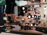
I had also decided I was going to make a couple modifications to the power supply, which everyone has acknowledged is the weak point of this player. I had some components on hand, so I came up with this plan (all on the primary side of the supply):
1) replace the input filtering film capacitor with Wima MP3-X2 type
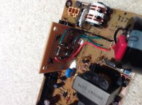
2) replace the IC bridge rectifier with good quality, high-speed rectifier diodes
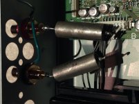
3) replace the smoothing capacitor with a 400v, 330uf monster
Here's how it played out:
1) easy enough
2) I created a bridge rectifier using the diodes on a small proto board. Had to mount it vertically to get it to fit. looks pretty good, I think.
3) the cap I used was pretty big, and it didn't fit, so I had to mount it horizontally, using lead wires. I also bypassed with a .01uf Wima.
Finally, time to put everything back together and test it out. Of course, in my haste, I never game the unit a good listen before doing these mods, so all I could do was compare to other players I had readily available. Overall, I really enjoy the sound. Very wide soundstage, great bass, really nice highs. But, shines in the mid-range.
All in all a fun project (especially because it was successful) that was completed over just a couple of days.
Check out the pics!
So, I've had my DVP-NS500V for years; bought new. It's been used sparingly, most recently as solely a DVD player for my young daughter. But, I've been itching to tinker with it, and when I decided to give it a go, I found this thread, which was tremendously helpful.
Most of my CD/DVD player mods simply bypass the output stage through .5-1 uf capacitors to newly installed, gold-plated RCAs. However, for this one, I was really intrigued with the idea of the more complex mod of replacing the op amp. And, I had a few SMD Burr Brown OPA2134's lying around, so what the heck!
I was a bit worried, however, as I've never had good luck removing/installing SMD ICs, likely because I don't have the right tools, and I'm usually impatient. But, I was determined this time to do it right.
I started by completely breaking down the unit, and removing all the boards (not that it was necessary, I just wanted to get a look at everything). The bulk of the work would be done on the audio board, and here was my 7-step plan:
1) remove the opamp driving stereo output (I decided to leave the 5.1 output as stock)
2) remove the stereo RCAs (which also meant removing the composite video, but oh well)
3) install Burr Brown OPA2134
4) add filter capacitors to the power/ground pins of the OPA2134
5) install gold-plated RCAs
6) use NOS paper-in-oil .5uf capacitors for output decoupling
7) take output directly from OPA2134 (pins 1 and 7) to caps to new RCAs
Here's how the plan was executed:
1) first, I patiently cut the pins of the existing opamp using a utility knife. Definitely not the right tool, but I worked slowly and was very careful. With the pins cut, as I was lifting the pins the IC just popped off. I was worried for a second that I broke a trace, but examination under the magnifying glass showed no damage. Whew!
2) Removing the existing stereo RCAs was very simple - significantly easier than on other units that I've worked with.
3) No for the tricky, delicate part - soldering the OPA2134 to the board. I tried to remove the remaining pieces of the original opamp pins using 30-watt iron, but was really worried about breaking the traces (as others have experienced with this unit), so after a few attempts, I just decided to solder the new opamp on top of the remaining pins. I cleaned the whole area with isopropyl alcohol, positioned the magnifying glass, and went to work. I first soldered the ground pin (BTW...I used very small gauge silver solder), just enough to secure the IC to the board. Then, I went to work on the other pins, again very patiently. It took about 15 minutes, but I got it done. It's not pretty, but it's good enough for my first SMD!
4) I had 1uf 50v electrolytics on hand and was a little worried that they'd be too big, but I used them anyway. Everything fit just fine.
5) The challenge with using new RCAs is that they end up being located under the audio board. Actually installing them was obviously easy, but I had to think ahead about the ground wire, and L/R output signal wires.
6) The position of the RCAs doesn't leave a lot of room, especially for larger capacitors, but I managed to orient them in such a way that the fit fine.
7) I decided to use some 30-gauge wire that I had from the Shack for the output signals. It's just easier to manipulate, even if it's a little more delicate. My point of tapping the output signal from the opamp was at the existing decoupling capacitors. Because I'm anal, and these caps were no unnecessary, I removed them. Unfortunately, in removing the left channel capacitor, I broke the trace. I attempted to scrape a bit of the board and solder the wire to the little bit of exposed trace, but that didn't work. I ended up having to trace the circuit back to a point closer to the opamp. It all worked out in the end.
The last step was to reassemble the audio board in the chassis, which was slightly challenging connecting everything under the board. But, I got it done, and all looked good.
I had also decided I was going to make a couple modifications to the power supply, which everyone has acknowledged is the weak point of this player. I had some components on hand, so I came up with this plan (all on the primary side of the supply):
1) replace the input filtering film capacitor with Wima MP3-X2 type
2) replace the IC bridge rectifier with good quality, high-speed rectifier diodes
3) replace the smoothing capacitor with a 400v, 330uf monster
Here's how it played out:
1) easy enough
2) I created a bridge rectifier using the diodes on a small proto board. Had to mount it vertically to get it to fit. looks pretty good, I think.
3) the cap I used was pretty big, and it didn't fit, so I had to mount it horizontally, using lead wires. I also bypassed with a .01uf Wima.
Finally, time to put everything back together and test it out. Of course, in my haste, I never game the unit a good listen before doing these mods, so all I could do was compare to other players I had readily available. Overall, I really enjoy the sound. Very wide soundstage, great bass, really nice highs. But, shines in the mid-range.
All in all a fun project (especially because it was successful) that was completed over just a couple of days.
Check out the pics!
Attachments

- Status
- Not open for further replies.
- Home
- Source & Line
- Digital Source
- my hacked-up Sony DVP-NS500V SACD player