". . . It is not the dogma of subjectivists but the dogma of physics . . . "
Seems the only dogma around here is from you Lumba.
Seems the only dogma around here is from you Lumba.
Hey?
Just meant my buds in Santa Clara probably have a few lost in their desks. 🙂
Hi,
as already fruitlessly stated:
Cascoding the cascode is pretty pointless. The anti-saturation network does not belong in pure audio, but could work as a commercial trick, what do you think, Bonzai?
Instead of circling around beta; topology, transistor type and impedances are more important for good amplifier design.
Impedance matching:
For the maximum transfer of power, the output impedance should be the same as the input impedance.
For the maximum transfer of current, the output impedance and the input impedance should be low.
For the maximum transfer of voltage, the output impedance should be low and the input impedance should be high.
Ideal port resistances:
Voltage input - infinite
Current input - zero
Voltage output - zero
Current output - infinite
Post 78 is an amazing demonstration of either wholesale misunderstanding or willful misconstruction
Hard to quote a quote containing post so I recommend opening in a new window:
http://www.diyaudio.com/forums/soli...as-linearity-investigation-4.html#post2014855
then actually read the references and see for yourselves
Distortion in power amplifiers, Part III: the voltage-amplifier stage | Audio DesignLine
Self’s VAS gain equation is in fact right on given his assumption of current mirror drive – for DC as Self explains: (later pages, you all do know how click on links?)
quite acceptable as a 1st order model: a “QED” approximation
those not getting it “in one” as presented can take baby steps: diff pair¤t mirror input stage provides i_diff current drive which causes a V in the CE VAS Qbe r_pi
Vbe=i_diff*r_pi
r_pi = beta/gm
and the voltage gain of the CE is gm*Rc
i_diff*(beta/gm)*gm*Rc = i_diff*beta*Rc
so it looks like beta*Rc is fine
Lumba’s further comments about nonlinear Ccb may make you think Self’s article’s analysis didn’t use the word impedance or figures containing Audio Precision distortion plots of real circuits with the 6dB/oct distortion rising out of the noise floor above 1 KHz being duly noted – try reading with your eyes and mind a little more open
The intro swipe at Hawksford is similarly pretty much completely wrong:
http://www.essex.ac.uk/csee/research/audio_lab/malcolmspubdocs/J10 Enhanced cascode.pdf
as anyone reading far enough to get to the discussion of z_cb, z_ce and the measured real circuit results @ 1,10,20, and 50 KHz can see
Hard to quote a quote containing post so I recommend opening in a new window:
http://www.diyaudio.com/forums/soli...as-linearity-investigation-4.html#post2014855
then actually read the references and see for yourselves
Distortion in power amplifiers, Part III: the voltage-amplifier stage | Audio DesignLine
Self’s VAS gain equation is in fact right on given his assumption of current mirror drive – for DC as Self explains: (later pages, you all do know how click on links?)
Equation 1 in the first article shows that the LF gain (i.e. the gain before Cdom is connected) is the product of input stage transconductance, Tr4 beta and the collector impedance Rc. The last two factors represent the VAS gain and therefore the amount of local NFB can be augmented by increasing either. Note that so long as the value of Cdom remains the same, the global feedback factor at HF is unchanged and so stability is not affected.
quite acceptable as a 1st order model: a “QED” approximation
those not getting it “in one” as presented can take baby steps: diff pair¤t mirror input stage provides i_diff current drive which causes a V in the CE VAS Qbe r_pi
Vbe=i_diff*r_pi
r_pi = beta/gm
and the voltage gain of the CE is gm*Rc
i_diff*(beta/gm)*gm*Rc = i_diff*beta*Rc
so it looks like beta*Rc is fine
Lumba’s further comments about nonlinear Ccb may make you think Self’s article’s analysis didn’t use the word impedance or figures containing Audio Precision distortion plots of real circuits with the 6dB/oct distortion rising out of the noise floor above 1 KHz being duly noted – try reading with your eyes and mind a little more open
The intro swipe at Hawksford is similarly pretty much completely wrong:
http://www.essex.ac.uk/csee/research/audio_lab/malcolmspubdocs/J10 Enhanced cascode.pdf
as anyone reading far enough to get to the discussion of z_cb, z_ce and the measured real circuit results @ 1,10,20, and 50 KHz can see
JCX,
whatzzza problem actually?
The LF gain of Self`s VAS linearized by local NFB is equal to the ratio Rc/Re. No beta as far as the eye can see.
whatzzza problem actually?
The LF gain of Self`s VAS linearized by local NFB is equal to the ratio Rc/Re. No beta as far as the eye can see.
Hi LumbaAndrew,
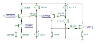
suggested topology, in consideration of function and transistor properties:
I'm not sure I understand correctly.
Is the input to the gate of T1?
And the output is from the drain of T2?
But that is connected to VS1, IS2 and R1, so the output voltage swing will be applied to these as well.
Is that right, or should those parts be connected to the positive rail?
Regards - Godfrey
Gate of T1 is input, T3 is cascode for T1, T4 is folded cascode VAS stage, source of T2 is output .
Ah, yes. Then it looks very good, except that T2 is driving 1 ohm at it's output. Perhaps a different value is intended for R8?
godfrey,
sorry about those flaws, my aim was something else than resistor values.
Yes, trolling like a moron. And that's a factual statement. If the moderators have a hissy fit with that they can eat my shorts.
Last edited:
Yes, trolling like a moron. And that's a factual statement. If the moderators have a hissy fit with that they can eat my shorts.
I bet you wrote this after you cut your finger 🙂 Nice job on the deck BTW.
Take it easy, Glen, why are you sulking? Girlfriend problems?
That´s not a working circuit, I just drew it in five minutes. Compose yourself, take a deep breath and start over, you have a long way to go.
That´s not a working circuit, I just drew it in five minutes. Compose yourself, take a deep breath and start over, you have a long way to go.
Good topic, Glen K.
I came here after google searching for 'folded cascode'.
This is because I am working/investigating in Spice with a
- symetrical input feeding into a 'vas' with
- cascoded folded cascode
(like diagram in your first post:
http://www.diyaudio.com/forums/atta...scode-vas-linearity-investigation-figure3.jpg )
- output buffert is one Class A Sziklai power stage
Thanks for very good stuff, Glen!
Good topic, Glen K.
I came here after google searching for 'folded cascode'.
This is because I am working/investigating in Spice with a
- symetrical input feeding into a 'vas' with
- cascoded folded cascode
(like diagram in your first post:
http://www.diyaudio.com/forums/atta...scode-vas-linearity-investigation-figure3.jpg )
- output buffert is one Class A Sziklai power stage
Thanks for very good stuff, Glen!
Hi Lineup
I agree, this is a very interesting thread and Glen is “in my opinion” ingenious.
BTW: you may have noticed that GK is no longer a member at this forum, so he is not able to answer your post.
Cheers
Stinius
- Status
- Not open for further replies.
- Home
- Amplifiers
- Solid State
- My folded-cascode VAS linearity investigation