Am I correct in thinking R12 is the cathode resistor?
If I am then my R12 = 1,237Ω
Cathode voltage is 298V after tube warmup.
That leaves me with 24mA of cathode current....Too much?
I have a solid 18mV DC on the R channel w/ just my blackberry driving it
With the preamp connected I have between .1-.9VDC on the output with the volume pot maxed and volume setting the same on the blackberry.
Last edited:
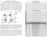
Reading through the manual here says that with 6CG7 (what I have) at 300V (What I Have) at 1k cathode you get 26mA.
As I said before, you do not have 300V on your tubes. You have 150V
Each triode sees only half of the B+. There are two triodes in each tube. The spec sheets are per triode.
Don't worry too much about trying to read the charts. That's the job of the designer.
With your tubes and 300V, 470R is the correct sort of cathode resistor. I know this because I have built about 10 aikidoes.
Woofer moving issue : OK the reason your woofer is moving is because some DC is getting to the woofer. As the power amp is DC coupled, any DC on the input will be amplified.
So first thing I would check is this : Is there any DC voltage at the preamp output? There should be absolutely none. The output is capacitor coupled, and it's connected to ground via a 1M resistor.
Also, with the preamp turned off (and left to cool down so no PSU voltage left), measure the resistance across the output. It should read 1 meg ohm. That's the value of the resistor that connects to ground.
btw, you are not experiencing motorboating. That is when you get a pop-pop-pop sound from your speakers.
One last question - does music make it through the preamp?
Yes, music makes it through the preamp and sounds quite good really.
Which resistor (R#) is the cathode resistor so I can be sure which to measure.
I have a 1.0uf capacitor on the output of the preamp.
I will measure for DCV on the preamp output after dinner (now).
Which resistor (R#) is the cathode resistor so I can be sure which to measure.
I have a 1.0uf capacitor on the output of the preamp.
I will measure for DCV on the preamp output after dinner (now).
Attachments
Am I correct in thinking R12 is the cathode resistor?
If I am then my R12 = 1,237Ω
Cathode voltage is 298V after tube warmup.
It would help if you posted a pic of the circuit diagram that you are referring to.
1) The cathode voltage is no way 298V. Your B+ might be. But the cathode is the tube connection that goes towards ground, not towards the B+ (that is the anode)
2) If you look at the aikido circuit, you see that each section (first, second) is composed of two triodes, and they basically span the power supply from B+ to ground. These two triodes are connected with two resistors. One goes between the tubes, from the anode of the bottom tube to the cathode of the top tube. Also there is one from the cathode of the bottom tube to ground.
These are the cathode resistors. They should be about 470R or thereabouts.
But I doubt that this is your problem...if it's working and playing music then chances are that it's OK.
You have two problems : hiss and woofer movement.
The hiss is likely a bad tube, so swap the tubes about and see if the hiss moves about.
I wrote about the woofer problem in my previous post.
Last edited:
My Output DCR is .997MΩ, GOOD.
My output DCmV is from -100mV to +50mV, It really dances around.
I'm not sure what diagram you are needing.
I have a scanner and I can scan the entire manual if you would like.
My output DCmV is from -100mV to +50mV, It really dances around.
I'm not sure what diagram you are needing.
I have a scanner and I can scan the entire manual if you would like.
Attachments
Last edited:
OK, I did some more poking around, I think my R4 is the cathode resistor.
On the left channel resistor I have only 97VDC on the right I have 163VDC (more like it).
Strange enough the hiss is louder on the left channel.
My R3's & R4's are 1kΩ.
On the left channel resistor I have only 97VDC on the right I have 163VDC (more like it).
Strange enough the hiss is louder on the left channel.
My R3's & R4's are 1kΩ.
Last edited:
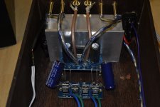
Here is a picture that shows the tubes and their resistors.
Attachments
Last edited:
SO, it appears that R3 & R7 are the cathode resistors here also.
How (exactly) do I measure the voltage you need to know.
I know this must sound dumb but when I make measurements from either side of those resistors to ground I get little to no voltage.
How (exactly) do I measure the voltage you need to know.
I know this must sound dumb but when I make measurements from either side of those resistors to ground I get little to no voltage.
Attachments

Last edited:
The circuit diagram you have posted there is called "Configuring the PCB as a headphone amp" and shows the normal output stage converted to a White Cathode Follower. Note that in your circuit, R22 should be a jumper (ie 0R) ,R10 should be 83.2k and R7 should be 470R. And C23 should be omitted.
Assuming that you have built the standard aikido circuit and not the headphone version, the cathode resistors are R3 and R4 for the first stage, and R6, R7 for the second stage.
1000R is OK for the first stage cathode resistors. For the second stage you'd want 470R
To measure the voltage across the resistors is simple. Put one multimeter lead on one end of the resistor, and put the second multimeter lead on the other end of the resistor. You should see about 470 x 0.01 = 4.7V across the resistors.
It might help if you can take a high res photo of the aikido board as you have built it, so we can see the resistors, etc.
Last edited:
Yes, I have built the standard Aikido NOT the headphone.
I merely posted that picture because it was the only diagram in the book that showed the R3,4,6&7.
Why do you think my voltages are all over the place? (Bad Solder)???
I merely posted that picture because it was the only diagram in the book that showed the R3,4,6&7.
Why do you think my voltages are all over the place? (Bad Solder)???
Last edited:
Why do you think my voltages are all over the place?
Not sure at the moment. I was trying to work out if the basic parameters of the circuit are correct. For instance, what value are your output tube cathode resistors. You said that your input tube ones are 1000R, but I'm not sure what the output stage's are.
OK then we need to know the voltage(s) across the resistors, so we can check that you are getting the right current flows.
So, assuming that the currents are correct I'd move on to trying to diagnose the problems.
Starting with the hiss. First, remove the first two tubes (input tubes, left and right). Power up and see if you get hiss. If you do, swap the output tubes. Test. Does the hiss change channel?
If the hiss is gone, replace the input tubes, test. Swap input tubes left to right. Test. These tests should give you an idea of which tube(s) are the problem. (I'm guessing that hiss is likely to be tube problem, as it normally is, and it's not likely to be VHF Oscillation as there's no feedback.
Diagnosing the woofer/DC problem. The really odd thing here is that you said that with the preamp powered off, you still get the woofer movement.
Try this test again, but measure the DC on the preamp output while you observe the woofer. Unplug the interconnect cables. Does the woofer go to normal? What is the voltage on preamp output now? Plug back in? What happens? What is voltage on output. If you short out the output, does the woofer return to normal?
That sort of thing...when trying to diagnose remotely, we need as much info as possible.
The problem might be bad soldering, but it could be lots of other things as well.
Thank you for your patience and help.
I will make those tests and observations tomorrow.
When the strange cone movement happens and I disconnect the Preamp the cone returns to neutral.
I will make those tests and observations tomorrow.
When the strange cone movement happens and I disconnect the Preamp the cone returns to neutral.
Yes....However I suspect that it was capacitors discharging that still allowed the cone movement.
Once the preamp was disconnected the cone returns to neutral.
I will recreate the circumstances and get more precise observations.
Once the preamp was disconnected the cone returns to neutral.
I will recreate the circumstances and get more precise observations.
Also, take a measurement on the output at the RCA jack and measure for DC on the output...try it with the aikido powered off and switch it on and observe DC for 30 seconds or so maybe start at the 2000 mV scale....
Also, do you have another amp to try out?
Also, do you have another amp to try out?
One other question- when you see the slow cone movement, do the channels track (i.e., the cones moving in synchrony) or are the cones moving differently?
OK, I noticed in the manual it says that you should use the highest value dropping resistor.
I'm using the 220V tap on my transformer and I could change to the 240V tap and use more dropping resistor.
Or....Maybe I have a bad capacitor???
How can I help diagnose this power supply problem?
I'm using the 220V tap on my transformer and I could change to the 240V tap and use more dropping resistor.
Or....Maybe I have a bad capacitor???
How can I help diagnose this power supply problem?
- Status
- Not open for further replies.
- Home
- Amplifiers
- Tubes / Valves
- My First Tube Preamp