Circlotron:
That is an ingenius way of making a CCS. Certainly the mother of CCSs at dc. Try putting a squarewave voltage across it - it may not be quite as good as your estimate, perhaps more the mother-in-law of CCSs?
Richard:
One way is to put the CCS on the +'ve rail and make the CFP using a pnp driver and nFet on the -'ve rail.
Where it's at today.
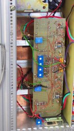
Righteo then. A few changes on the weekend. Added a hi and low pass filter on the input to keep out RF and sub-audio. Ditched the source resistor and bypass cap - was a source of LF phase shift and possible instability. Same with cap feeding gate that has now been shifted to outside the feedback loop. One of the most significant canges though was to make a second feedback loop inside the first. Previously we had a gain of about 3000 closed with global feedback. It worked ok but I wasn't super happy with it. Now a 1uF and 330k feed back to the 3k3 and the gate to set the driver fet gain at 100, and this gain is then closed from the output fet through the 33k back to the 3k3 setting the overall gain at a little below 10. If the inner closed loop gain was very high, not just 100, the outer loop gain would be closer to 10.
When the amp is driven into clipping and you look at the output fet gate drive, as soon as the clipping occurs the gate gets driven way higher as you would expect, but only at a rate of x100, not x3000 as before. This way the first stage still remains sensible because it doesn't loose all feedback, and when the output comes out of clipping the output waveform is very clean and controlled. There is no ringing or sudden drop in the waveform as it begins to come down, it just moves cleanly away from the clip point.
How does it sound? At the moment I think it sounds very good, clean and easy to listen too. Plenty of fine detail. Wind it up loud and it doesn't hurt your ears or sound stressed. The sound just seems to get closer. I have started to assemble the whole thing now so more reports and pictures as I progress.
GP.
Attachments
Pieces are starting to come together now. Junk turning into amplifier. Entropy rolling uphill. Every time I do a bit more chassis bashing I shudder thinking about it before I start because doing this sort of thing is not my speciality at all. I can design circuits in my sleep, but making them physically practical in the real world i.e. putting them in a box -  Very scary stuff.
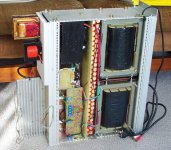
Orange capacitors you can see have another two rows hidden underneath. Two big chokes up the front, 500va black transformer at bottom lef inside chassis corner, across back at very left corner is 4.7H choke for 145v 100mA driver stage supply, next is 1.35mH choke (wound with plasic insulated wire) for 30v 7 amp main (choke input) supply. 19 inch rack chassis with pen for scale. Just busting to get it finished and going.
GP.
Very scary stuff. Orange capacitors you can see have another two rows hidden underneath. Two big chokes up the front, 500va black transformer at bottom lef inside chassis corner, across back at very left corner is 4.7H choke for 145v 100mA driver stage supply, next is 1.35mH choke (wound with plasic insulated wire) for 30v 7 amp main (choke input) supply. 19 inch rack chassis with pen for scale. Just busting to get it finished and going.
GP.
Attachments

Like uh, heavy man.
Well, after going out to the shed for a while and doing a bit of chassis wiring for a w hile I got to wondering just how heavy is this behemoth? So I went and got the bathroom scales and finally got them underneath. It weighs in at 51 kg. That's a hundred and twelve pounds, a hundredweight! And it's not finished yet...
GP.
Well, after going out to the shed for a while and doing a bit of chassis wiring for a w hile I got to wondering just how heavy is this behemoth? So I went and got the bathroom scales and finally got them underneath. It weighs in at 51 kg. That's a hundred and twelve pounds, a hundredweight!
And it's not finished yet...GP.
The dual row of (visible) orange caps look like soldiers standing at attention. 🙂 Quite impressive!
What capacitance and working voltage are they?
Erik
What capacitance and working voltage are they?
Erik
Wow, thanks Nelson. I appreciate that. 🙂 🙂
eLarson, the caps are 2200uF 35v, total of 104 of them. Not a calculated quantity, just that it was the amount that fitted neatly into the chassis. They are low esr switchmode type.
GP.
eLarson, the caps are 2200uF 35v, total of 104 of them. Not a calculated quantity, just that it was the amount that fitted neatly into the chassis. They are low esr switchmode type.
GP.
Finished finally.
I got this jigger fished about two weeks ago and it sounds just fine. Bias servo is done to keep the current at a constant 3.5 amps despite temperature changes etc. It sounds nice and relaxed and easy to listen to. Residual noise is very low; an ear right up to the speaker and hold my breath to hear anything.
This circuit is not copyright by me, so as far as I am concerned it is now in the public domain. Anyone can use it. If anyone does make one then let me know because I would be most chuffed.😀
Attachments
Nelson Pass said:You do nice work, Circlotron!
🙂
Hi, I say the same! I like when crazy ideas are converted into equally crazy things. It's a masterpiece of it's kind.

Circlotron
The output stage of your beatiful design, it says on the schematic that the line is 30V, 3.5A.
Is this current set only by the input at the gate of the FET, or do you have a constant current source in the PS line?
IOW, is it enough with a FET and an inductor as the follower?
For a simple circuit, could I use a bipolar PS and ground the gate for a rining circuit.. guess no, somehow the current must be set to a working point.. how?
I thik I understand a CCS or resistor loaded FET follower but not this inductor thing 🙂
/Peter
Pathos amp
It happened so, that i listened to Pathos amplifier in a show room
and i could not believe my ears. Really dynamic, transparent, robust, not forgiving. I compared it with tubes, semiconductors and other hybrids, but it was quite away from all. What a design!(imean what an electronic design, to discriminate from the aesthetic design, which is also top) If someone can draw a diagram in the lines of Pathos, i would be glad to try to build one out of it. The amp i see in this thread, seems to be realy something. Congratulations. But think of your fellows that are suffering from pain on their back!
Re: Circlotron
Pan said:The output stage of your beatiful design, it says on the schematic that the line is 30V, 3.5A.
In real life it is closer to 27.7 volts.
Is this current set only by the input at the gate of the FET,
Yes, typically about 5.5 volts, but varies with temperature.
IOW, is it enough with a FET and an inductor as the follower?
For a simple circuit, could I use a bipolar PS and ground the gate for a rining circuit.. guess no, somehow the current must be set to a working point.. how?
The opamp cct down the bottom keeps the average dc voltage dropped across the choke resistance (a bit under 100 milli-ohms) constant, therefore the fet and choke dc current stays constant.
I thik I understand a CCS or resistor loaded FET follower but not this inductor thing 🙂 It is just like a tube class A output stage with transformer but the load is at the bottom instead of the top so you automatically have 100% negative feedback for this stage. Also, no voltage gain.
/Peter
Re: Circlotron
I don't get it......
halo - thinks asomething is hard to catch here
so what is the comment on this?Pan said:The output stage of your beatiful design, it says on the schematic that the line is 30V, 3.5A.
Is this current set only by the input at the gate of the FET, or do you have a constant current source in the PS line?
IOW, is it enough with a FET and an inductor as the follower?
For a simple circuit, could I use a bipolar PS and ground the gate for a rining circuit.. guess no, somehow the current must be set to a working point.. how?
I thik I understand a CCS or resistor loaded FET follower but not this inductor thing 🙂
/Peter
I don't get it......
halo - thinks asomething is hard to catch here
I thought that a FET lookig into a inductor would be like a short at DC current.
In the SOZ for example. I understand that no matter how high you bias the FET´s the power resistors ultimately limits the current, and the FET is "safe".
I thought there was a need for something to "control" the current more than the inductor and it´s DC resistance and the bias voltage at the gate.
I´m no EE appearantly 😀
A question: If a FET is connected to a "single ended" power-supply (a battery for instance), and a voltage divider put on half the PS Voltage to the gate of the FET, what happens?
Is this a "CCS" and in such case, how do I calculate the current?
Guess I should get some good books and refresh my memory on how electronics works 🙂
/Peter
Circlotron
Where you get the 5V bias from?
If the bias Voltage would be raised to half the power supply, what will happen, the FET can take it and the ouputstage idles a higher current?
I think I slowly beginning to understand parts of the circuit. The DC offset you have is from the resistance of the inductor wire right? Zero Ohm in the wire of the coil, and no DC offset?
Does anyone now aprox. what distortion levels one can get from just the FET follower stage if driven from low impedance and everything is optimized? (no loop feedback).
Help me understand these circuits and I will be grateful forever 🙂
/Peter
MOSFETS and stuff
If the power supply voltage is say >12v then the operating current of the MOSFET is dependent on the gate voltage. Also remember that a gate of a MOSFET can only handle about 20v.
Voltage at the output is dependent (in this case) on the DCR of the inductor.
Distortion is very low... only if a driver stage is capable of handling the Ciss at high frequencies....
Hope that helps.....
"If the power supply voltage is say >12v then the operating current of the MOSFET is dependent on the gate voltage. Also remember that a gate of a MOSFET can only handle about 20v."
If we apply 6V on the gate on this mosfet that runs on a 12V supply, how do I calculate the current? Let´s assume that the mosfet is allone in the circuit.
About the maximum gate to source voltage, I thought that only very fast transients destroyed the mosfet if 20V or above?
If the gate only can handle up to 20V sinewave, then it´s not possible to build as powerful (high voltage swing out) amps with mosfet as with BJT´s.. or?
Or is it only follwers that has limitations when using mosfets, and high power can be had if circuit is something else than a "simple" follower? Nah, that can´t be the case. I have seen several desings on the net (and in books I think) that uses P and N channel mosfets as complementary followers...???
Last question; Is it possible to connect a resistor direct between gate and source in order to damp the energy stored by the capacitance? In this case it would be similar to the emitter resistor between a BJT emitter-follower and its driver?
Say about 100-200 Ohm and the source can handle it without problem?
I will stop asking these questions as soon as I find some nice books or sites at the web , really... 🙂
/Peter
- Status
- Not open for further replies.
- Home
- Amplifiers
- Solid State
- My first ever Class A amp.