Hi Tyimo!
SOme calculations -
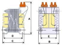
your proposal (0.25 mm air gap) saturates the core three times over
at 3A and gives you 0.55 H
increase the air gap to 1.25 mm javascript:smilie(' ')
')
bigeyesgives 117 mH and 0.7
increase the air gap to 1.5 mm gives 97 mH and 0.6T at 3 amp
I've taken your core dimensions and plugged them in. I've assumed that the iron permeability is 15,000 but even at 5,000 the results won't be too different.
I reckon you need to run the core at a low mag. if it is D.C. biased.
hope this helps?
cheers
John
SOme calculations -
your proposal (0.25 mm air gap) saturates the core three times over
at 3A and gives you 0.55 H
increase the air gap to 1.25 mm javascript:smilie('
')bigeyesgives 117 mH and 0.7
increase the air gap to 1.5 mm gives 97 mH and 0.6T at 3 amp
I've taken your core dimensions and plugged them in. I've assumed that the iron permeability is 15,000 but even at 5,000 the results won't be too different.
I reckon you need to run the core at a low mag. if it is D.C. biased.
hope this helps?
cheers
John
Hi John!
I got my 127mH chokes!🙂
Unfortunately they are made with only EI108 (outside: 108x90x40). Wire: 1.4mm
What do you think can they drive 3A???
How can I measure the very correct resistance of the choke? My multimeter is not perfect under 1 Ohm.
Greets:
Tyimo
I got my 127mH chokes!🙂
Unfortunately they are made with only EI108 (outside: 108x90x40). Wire: 1.4mm
What do you think can they drive 3A???
How can I measure the very correct resistance of the choke? My multimeter is not perfect under 1 Ohm.
Greets:
Tyimo
Hi Tyimo
Wire is able to carry 3A no probs.
Can't tell whether your coil will saturate or not without knowing the airgap/turns etc.
You can measure your coil's resistance with the old Kelvin method. If you have a 1 amp supply (or you can set a transistor up as a current source at 1A if you have, say, a 2N3055 on a heatsink) attach the terminals to the coil. Measure the volts across the coil with a voltmeter. Best to attach a power diode in reverse to catch the inductive spike when you disconnect. Stored energy is going to be quite a zap.
You can also check the saturation if you use a transistor as a current source. You can just as easily use this as your Class A amp. and modulate the input to the base if you have an oscillator and oscilloscope. Set the current to 1A and modulate the base to give about 100 mA variation (e.g. at 1 kHz). The output across the choke should be measured with a load (eg 8 ohm) in parallel (no diode) using the oscilloscope. Increase the current to 2 A (modulation could be 200 mA) ..and so on. When you see the choke output fall or clip instead of increasing that's the saturation limit. Then you'll have to run the amp at half this or change the airgap...
cheers
John
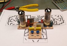
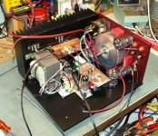
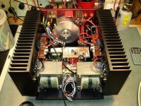
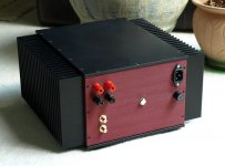
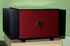
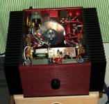
my choke loaded amp
I wonder if I can add to this thread?
It took me two years to finish my example of this amp.
Everything is a hinder, getting the heat sinks, the panel's, the mechanical work ,the parts , brushing the aluminum parts and the anodizing. This is a simple amp made with a Russian equivalent of ECL84 which is the 6F4P as the driver and the 2SK82 vfet transistor, came off the ebay from a Singapore dealer. The general size of the amp and the heath sinks ,only support 10W/CH output, still the weight is up to 19kg and power consumption over 100W.
This is not a green amplifier. I will upload some pictures.
Miklos
Attachments
Member
Joined 2009
Paid Member
Thanks guys,
Circlotron, in a way I envy your killer chokes, with the zero DC resistance, but then I wouldn't be able to move the amp.🙂
Circlotron, in a way I envy your killer chokes, with the zero DC resistance, but then I wouldn't be able to move the amp.🙂
Another thread back to life!
Tyimo did you get your amp working?
Still seems we need a big core for these amps. Miklos can you move your amp without a forklift?
John
Tyimo did you get your amp working?
Still seems we need a big core for these amps. Miklos can you move your amp without a forklift?
John
Hi John!
Nice to see you!
Yes, since that time I built 4-5 choke loaded mosfet follower amplifier with very big success. Mine is also a kind of hybrid, but I use an interstage coupled tube driver stage. I have 15 and 36W versions.
Greets:
Tyimo
Nice to see you!
Yes, since that time I built 4-5 choke loaded mosfet follower amplifier with very big success. Mine is also a kind of hybrid, but I use an interstage coupled tube driver stage. I have 15 and 36W versions.
Greets:
Tyimo
Another thread back to life!
Tyimo did you get your amp working?
Still seems we need a big core for these amps. Miklos can you move your amp without a forklift?
John
19kg, I can lift it, but won't walk far with it.
If one would use a powered sub ,than this amp could get away with smaller chokes.
- Status
- Not open for further replies.
- Home
- Amplifiers
- Solid State
- My first ever Class A amp.