That looks like you have the load resistor in series with the output. It should go across the output as if it were a speaker or headphone.
So, from output to GND is not correct?
Each RCA connector is one "headphone driver", Y-cable.
Yes, output to ground after the cap. The picture looks like it is in series with the ground to the connector 🙂
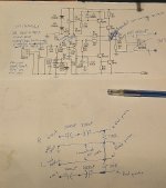
This second diagram shows the idea of making the servo a 'light action' type with limited range. There is now a conventional offset adjust (lower right). Now you trim the output of the opamp to zero volts, to put it in the centre of the range it can correct.

This second diagram shows the idea of making the servo a 'light action' type with limited range. There is now a conventional offset adjust (lower right). Now you trim the output of the opamp to zero volts, to put it in the centre of the range it can correct.
Attachments
Yes, output to ground after the cap. The picture looks like it is in series with the ground to the connector 🙂
This second diagram shows the idea of making the servo a 'light action' type with limited range. There is now a conventional offset adjust (lower right). Now you trim the output of the opamp to zero volts, to put it in the centre of the range it can correct.
View attachment 521166
Thanks, your help is greatly appreciated 🙂
The load resistors is soldered between signal (pin) and gnd on the RCA connector. That would make it in series signal - resistor - gnd.
If I took the TIP41C's off-board, and used large heatsinks...the dc drift would be considerably less, correct?
The heatsinks I had in mind.
An externally hosted image should be here but it was not working when we last tested it.
I could, I suppose, get them to fit onboard the PCB, but that would mean re-locating outputs and a few other things.
With the TIP41C's off-board, I could take the signal to the DC servo directly off Q1 emitter if that would be preferable.
Edit: Output resistors was changed to 68R from 2R2 as suggested in the JHL/JLH thread. (R7 on the schematic I posted earlier)
Last edited:
Draw what you have on paper. Post a pic of that and a pic showing the amp.
Post pic details of where your conections are and how they were made.
Show where you measured a voltage. Add labels to your pics, so that we can talk about specific POINTS and not become confused.
Post pic details of where your conections are and how they were made.
Show where you measured a voltage. Add labels to your pics, so that we can talk about specific POINTS and not become confused.
Draw what you have on paper. Post a pic of that and a pic showing the amp.
Post pic details of where your conections are and how they were made.
Show where you measured a voltage. Add labels to your pics, so that we can talk about specific POINTS and not become confused.
Will do 🙂
Schem with the changes I've made.
Empty PCB, the caps with polarity shown in the wrong direction on the silkscreen are the two 100uF's closest tp the outputs. There I have 470uF Rubycon ZL. All other 100uF spots are populated with 180uF Elna RJH's.
An externally hosted image should be here but it was not working when we last tested it.
That looks OK. The output must be at zero volts with the coupling cap... but you need the output to have a load resistor to ground, in other words a resistor across the point you have marked 'out'.
Your servo 'feed in' point is OK as long as you feed in via a high value resistor maintaining the approx 220k R19 value.
Your servo 'feed in' point is OK as long as you feed in via a high value resistor maintaining the approx 220k R19 value.
That looks OK. The output must be at zero volts with the coupling cap... but you need the output to have a load resistor to ground, in other words a resistor across the point you have marked 'out'.
Your servo 'feed in' point is OK as long as you feed in via a high value resistor maintaining the approx 220k R19 value.
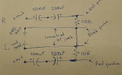
Ok, so the load resistors I now have on RCA connectors are wrong?
I figured the signal goes straight from the cap to the centerpin of the RCA, ground goes straight to gnd on the RCA...that I might as well, for convinience sake put the resistors between the pins and gnd's on the RCA connectors I plugged in to the 3.5mm stereo to 2x RCA cable I've used to test/measure more easily.
In other words
L
\
110R
/
GND
\
110R
/
R
Taking my measurements between L & GND and R & GND.
Yes, the resistor has to go between the output and ground. Do that and your 'offset' will be zero volts within second or two.
Yes, the resistor has to go between the output and ground. Do that and your 'offset' will be zero volts within second or two.
That's where I've had the resistors for the test yesterday(?).
Then it took alot more than a second or two, though it went alot faster than when I tried it without load the day before.
I'm a bit confused as to why it's not behaving as predicted?
DC-servo, If I use...say 330K or larger as output resistor from the DC-servo I can hook it up as I showed?
Non-inverting design?
So something like 1Meg input resistor to non-inv input and a cap between non-inv input and gnd. Resistor to gnd from inv.input and a cap between inv.input and output pin followed by 330K or larger output resistor to "injection point".
Does that sound about right?
Btw, was going to test the jfet + diamond buffer mounted on a breadboard today having made the changes suggested to the Jfet board(10K input resistor and 1uF to gnd)
An externally hosted image should be here but it was not working when we last tested it.
For some reason I got nothing from the transformer (12-0-12VAC 1500mA).
Since the temporary LM317/337 reg had two bridge rectifiers and I didn't want to power on the solderstation again, I made a Y-connection of the centre tap. That obviously didn't work. The only "free" dual secondary I have available now is a 2x15VAC 10VA, and that is too weak I think.
So tomorrow, I'll need to re-do the LM317/337 board using only one bridge rectifier.
Funny thing is I can almost swear I've done the Y-cable thing before and had it work...
The servo must be an inverting type for this amp. Take the case of the offset rising. In order to correct that the servo must drive the input more negative, and if the offset were going off in a negative direction then the servo must drive the input more positive.
So the servo must be inverting for this amplifier.
You are best drawing any circuit changes on the circuit diagram, that way it all makes sense much more easily 🙂
When you have the output AC coupled, the voltage across the load must settle to zero in a a second or so... it can't not do... laws of physics and all. So draw what you have as a circuit diagram, then it will make sense.
Now if by chance the output really does seem to take ages to settle to zero, even when AC coupled (and with a load resistor) then something else such as high frequency instability is going on.
The servo must be an inverting type for this amp. Take the case of the offset rising. In order to correct that the servo must drive the input more negative, and if the offset were going off in a negative direction then the servo must drive the input more positive.
So the servo must be inverting for this amplifier.
You are best drawing any circuit changes on the circuit diagram, that way it all makes sense much more easily 🙂
When you have the output AC coupled, the voltage across the load must settle to zero in a a second or so... it can't not do... laws of physics and all. So draw what you have as a circuit diagram, then it will make sense.
Now if by chance the output really does seem to take ages to settle to zero, even when AC coupled (and with a load resistor) then something else such as high frequency instability is going on.
That makes sense, and taught me something new 🙂
Inverted it is.
I'll draw up how the output is connected.
I don't have anything on the inputs, could it be oscillating causing the offset?
Middle diagram  that's correct.
Now... if there is a change in voltage away from zero then there are a couple of possibilities. One is that the rails are changing slightly (but they are regulated aren't they ?) Any change would reflect in the amp output and couple via the cap to give a constantly fluctuating voltage. If they are regulated though then that shouldn't happen but its still possible depending on the amp grounding scheme and whether any PSU voltage change can alter the grounds in relation to other parts of the circuit.
Secondly, it could be oscillation but that is a bit unlikely at such a low level you are seeing.
Keeping your meter black lead where it is, do you see any changes in the supply voltage ? Even a millivolt or two change will reflect onto the output with this type of design.
And ultimately, what you are measuring isn't an 'offset' in the normal sense because you can never get a constant DC voltage at the output.
that's correct.Now... if there is a change in voltage away from zero then there are a couple of possibilities. One is that the rails are changing slightly (but they are regulated aren't they ?) Any change would reflect in the amp output and couple via the cap to give a constantly fluctuating voltage. If they are regulated though then that shouldn't happen but its still possible depending on the amp grounding scheme and whether any PSU voltage change can alter the grounds in relation to other parts of the circuit.
Secondly, it could be oscillation but that is a bit unlikely at such a low level you are seeing.
Keeping your meter black lead where it is, do you see any changes in the supply voltage ? Even a millivolt or two change will reflect onto the output with this type of design.
And ultimately, what you are measuring isn't an 'offset' in the normal sense because you can never get a constant DC voltage at the output.
Middle diagram
Now... if there is a change in voltage away from zero then there are a couple of possibilities. One is that the rails are changing slightly (but they are regulated aren't they ?) Any change would reflect in the amp output and couple via the cap to give a constantly fluctuating voltage. If they are regulated though then that shouldn't happen but its still possible depending on the amp grounding scheme and whether any PSU voltage change can alter the grounds in relation to other parts of the circuit.
Secondly, it could be oscillation but that is a bit unlikely at such a low level you are seeing.
Keeping your meter black lead where it is, do you see any changes in the supply voltage ? Even a millivolt or two change will reflect onto the output with this type of design.
And ultimately, what you are measuring isn't an 'offset' in the normal sense because you can never get a constant DC voltage at the output.
The PS is regulated, by the awful 7812/7912 for now.
I'll try to measure if there's any variations in supply voltage. Right now I can't do that though as I'm currently making meatballs and listening to an audiobook lol.
Low level, well low with large output caps, without them not so much.
The design must be biased rather high considering the heat produced by the headamp. You can feel it 30cm or so away from it (with open enclosure).
I wish I could use super regulators or similar, but current demands of this circuit is way too high.
Btw, while looking around at opamps and info about them (for my "own" headamp), I came across a site explaining how to bias them in to class A using jfet CCS.
Don't know how good this is or how much of a differense it makes to SQ, but I bet it beats biasing opamps using Resistors.
Ordered a few 2N5484't try it atleast, they aren't expensive so no big loss should it be a dumb idea.
Very useful devices the 78/79 series of regulators. This could be worth a try... connect another load resistor (say 1k) to the same ground point you are using in the middle diagram, but this time connect the other end of the resistor to a large electrolytic (1000uf to 5000uf) and connect the other end of that to the positive rail. Now see if you can observe any voltage across the resistor over time. Do the same test for the negative rail (and watch the polarity of the cap). Any change in DC voltage will reflect in a reading across the resistor.
Opamps have very limited current source/sink capability and so biasing to class A is really only useful at line level impedances.
Opamps have very limited current source/sink capability and so biasing to class A is really only useful at line level impedances.
Very useful devices the 78/79 series of regulators. This could be worth a try... connect another load resistor (say 1k) to the same ground point you are using in the middle diagram, but this time connect the other end of the resistor to a large electrolytic (1000uf to 5000uf) and connect the other end of that to the positive rail. Now see if you can observe any voltage across the resistor over time. Do the same test for the negative rail (and watch the polarity of the cap). Any change in DC voltage will reflect in a reading across the resistor.
Opamps have very limited current source/sink capability and so biasing to class A is really only useful at line level impedances.
I don't really like them, they are easy enough to use, but SQ?
So, 1K in series with something like 4700uF to pos rail, and the same for neg, but with the cap the other way around.
Got two of unknown quality with a pair of LT1083 PCB's.
Could I do both at once? + cap - 1K GND 1K + cap - ?
I only have one DMM, something that has left me swearing alot lately..but I could simply move red probe from 1K to 1K and keep an eye on the DMM?
Yes, you can rig both up at once. It just might show something.
Will do.
Also need to figure out values for an inv. DC-servo.
An externally hosted image should be here but it was not working when we last tested it.
Can I keep the circuit as is, take signal from Q3 emitter to DC-servo?
Inject output from DC-servo to junktion R11, R19 and C13?
Or, would it be better to inject it on the side of R11 facing Q5?
Or, should I as previously suggested replace R19 with 2x 100K and inject DC-servo out to the midpoint of these?
Btw, what, if anything can be added/changed in this circuit to improve stability?
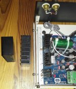
Also, when taking the headamp apart anyway, would there be anything to be gained from replacing the heatsinks with these?
(See attached pic)
Attachments
Q3 emitter/R5 junction is the correct take off place for a servo.
Have a look at post #82. I think that would be my preferred way of adding servo correction. Make it very light acting so that it just trims the error rather than the servo being the source of the total bias voltage needed.
R6 should be in the 1 to 2.2meg region.
Back in a bit 🙂
Have a look at post #82. I think that would be my preferred way of adding servo correction. Make it very light acting so that it just trims the error rather than the servo being the source of the total bias voltage needed.
R6 should be in the 1 to 2.2meg region.
Back in a bit 🙂
- Status
- Not open for further replies.
- Home
- Amplifiers
- Headphone Systems
- "My" first design headamp, DC-servo question