Hi,
Getting to the bottom of why the DM x/o did not work should be your main priority.
rgds, sreten.
Getting to the bottom of why the DM x/o did not work should be your main priority.
rgds, sreten.
Hi,
Getting to the bottom of why the DM x/o did not work should be your main priority.
rgds, sreten.
Well, I understand your point.
I also would like to know why it is not working in my set.
Maybe the crossover was designed with other cabinets in mind (wild guess).
Theoretically, when I input Dennis crossover values in the Boxsim, I get a very uniform mixed response from the group, even in the xover freqs range.
What puzzles me even more is that in my cabinets, (respecting Paul design) the tweeter high freqs are not there.
I can hear a lot of low and middle freqs but the high freqs are almost off.
It all sounds like, "inside a metallic can" with a boom bass. (reversing the tweeter polarity didn't solve it)
It becomes better when I remove the L-Pad but then its all unaligned.
I've been trying to fix this in the new simulations (Boxsim) but it seems almost an impossible mission.
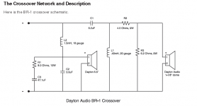
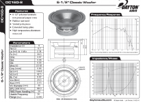
I need to test Paul's crossover design first and BR1-Dayton original kit crossover as well (the base from where Dennis started his own version - (image on attach)) to be able to create a valid reference point and restart from there.
Like you probably already know, beside all theory and mathematics there is also a lot of trial and error on the mix for me. 😱
Anyway, thanks for the focus reminder.
Attachments
Hi,
Your priority should be to work out what is wrong with the DM
x/o. Removing the L-pad should be a total disaster area.
Do some online hearing tests to remove you from the equation.
FWIW at 56 I have mild hearing loss and can't hear above 13KHz.
15 years ago I accompanied someone ten years my junior who
wanted advice when listening to speakers to buy them. I found
his preferences inexplicable. Turned out his hearing was shot *
at the top end, though with little hearing loss he did not know.
rgds, sreten.
* He reckoned due to artillery in his Greek military service.
Last edited:
Hi,
Do some online hearing tests to remove you from the equation.
FWIW at 56 I have mild hearing loss and can't hear above 13KHz.
Fortunately I do such hearing tests, every two years.
It is mandatory for my job.
They say I can hear all frequencies with minimum dB fluctuation along the full audible scale.
Maybe that's why I have trouble to get to sleep.
I can hear almost everything that is happening in my neighbors houses, the cats, dogs, people, everything in the neighbor area.
I'm glad that my neighborhood is a dead-end-road place, else, I probably had gone mad already.
I get your point, but I promise, I'm not the issue... well, second thought, maybe I am, only because I can hear almost everything that good.
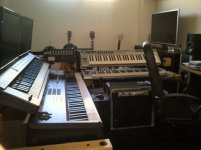
Oh, yes, I'm also a composer, so, I pay much attention to all the sound details, in music. 😱
Here you have my small home studio hole (picture in attach).
Attachments
Cradeldorf's suggestion is plausible though it may seem out there.
Example.. using simple ongoing measurements of the drivers separately and together while performing component substitutions will give you the same (two dimensional at least) result as a crossover simulator would. It's the same thing after all.
Example.. using simple ongoing measurements of the drivers separately and together while performing component substitutions will give you the same (two dimensional at least) result as a crossover simulator would. It's the same thing after all.
xover Version 2
Ok,
Many thanks for the tip AllenB, unfortunately I have not so much material and experience to try doing it by "guess". I wish.
I spend the last day trying to mess with the crossover.
I changed some values from the original and so far this is the best I could came with.
What do you think of these curves? (see attached)
Are all fine, or should I try to reach other values?
How about the impedance (Ohm) is the curve good to an 8ohm output amp?
Many thanks for your thoughts.
Attachments
Last edited:
Usually I do one driver at a time and get it to sound good then try to add the next one and keep fiddling until it all blends. :/ I know it seems kinda bass ackwards but i get to where I was going. I sent you a PM Ben.
Last edited:
This is how i designed my cross-over for my 2-way TL FS speakers,
1. I first build the TL box with the published TS parameters of the woofer.
2. I mounted the woofer in the box first without any stuffing and measured its impedance and phase using Room Equalizer Wizard using the impedance zig.
3. I stuffed the box with the required stuffing density and again measured the woofer impedance and phase using REW.
4. Then measured the tweeter impedance and phase after mounting them on the box.
5. I simulated the impedance and phase of the woofer and tweeter in a driver simulator to get its FRD and ZMA values.
6. I then imported these FRD and ZMA values in a cross-over simulator and designed the crossover.
7. The important things to note in the crossover simulator is to keep an eye on not only the Frequency Response and Impedance curves but also on the impedance phase, filter phase and transfer function simultaneously to get the perfect balance.
8. After getting the correct simulation i build the crossover and gain measured the speaker system impedance and phase.
9. I tweaked the component value to get witin 5% of tolerance of the simulated and measured value.
10 As i am measuring only the impedance and phase of the speaker system and since FR is a function of impedance and phase (FR = f(Z & Phase)) getting them within 5% of measured and simulated value, i do not have to measure the FR of the speaker system. I can rely on the simulated FR curve.
This method not only saved me time but also allowed me to perfect my design.
This is how i designed my cross-over for my 2-way TL FS speakers,
This method not only saved me time but also allowed me to perfect my design.
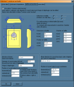
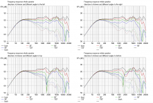
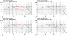
I understand perfectly, yet, this little free software I now use (recommended by tusker), includes the box/cabinet/enclosure design and wool too.
So, you can pretty much get something, virtually close to your method.
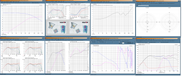
Yes, this software also reports all the graph analyses you require. (see attached images)
Attachments
Hi Ben,
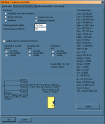
just a brief comment to your simulations: It looks like the resolution is set to 'coarse', you may want to change this to 'fine' (File -> Project properties). Further I suggest to change the scale of the Y axis to cover only 50 dB (50 – 100 dB) and 50 Ohms (Options -> View options). This will give you more significant results.
just a brief comment to your simulations: It looks like the resolution is set to 'coarse', you may want to change this to 'fine' (File -> Project properties). Further I suggest to change the scale of the Y axis to cover only 50 dB (50 – 100 dB) and 50 Ohms (Options -> View options). This will give you more significant results.
Hi Ben,
just a brief comment to your simulations: It looks like the resolution is set to 'coarse', you may want to change this to 'fine' (File -> Project properties). Further I suggest to change the scale of the Y axis to cover only 50 dB (50 – 100 dB) and 50 Ohms (Options -> View options). This will give you more significant results.
Good advice.
Will do that. 😉
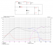
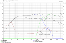
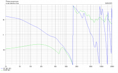
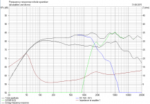
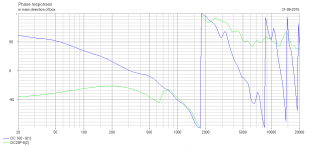
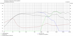
Ok, after review some "wrong" parameters I added to Boxsim (thanks to Lojzek for the help), I'm stuck at this point.
To keep the inductance and phase values sync I end creating a slope in the impedance.
Also frequencies in the xover zone are not coming very linear.
Any help would be appreciated.
See attached images.
If you use Boxsim, you can find a project file in attach (includes the drives data), just unzip the folders and add them to your BoxSim installation.
Then you'll find a new project called "Ben_DC28F-8_NEW_2ndOrder.BPJ". Load and check it out.
Attachments
To keep the inductance and phase values sync I end creating a slope in the impedance.
An increase in the impedance at the crossover is not uncommon. The simple answer could be that it represents the lost power, where each driver is down 6dB ( quarter power).
Unfortuntely it isn't always that simple, but fortunately it doesn't always matter becuse although some issues will be reflected in the impedance, there are some aspects of the impedanc that don't directly relate to the quality of a crossover.
I occasionally consider the effect this will have on an amplifier and make corrections (without affecting the crossover). This isn't strictly necessary.
I would however be concerned with the wiggles around 2kHz.
I would however be concerned with the wiggles around 2kHz.
Thank you AllenB.
Yea, I'm concerned about that too.
I'm not sure what to do about it... I guess I need keep trying to change some elements values.
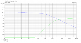
Could you show the tweeter impedance on its own without crossover?
Hi AllenB,
Many thanks for your interest and time.
In attach you can find a ZIP file with all relevant data, including the FRD and ZMS files of both drivers (Woofer DC160 and Tweeter DC28F).
After unzip the mail archive, you'll find both drivers folders.
Inside each driver folder, there is a GRAPH folder where you can find the Dayton measures (impedance graphics) and any relevant data needed to be used in any crossover simulation software.
Again, many thanks for taking the time.
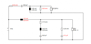
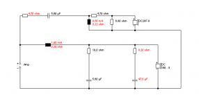
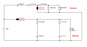
I've been trying to improve this mess. Here you have my most recent effort (crossover) and the result (response curves) to it (images in attach).
Attachments
After unzip the mail archive, you'll find both drivers folders.
Well, this is not an email. Silly me.
What I meant to say, is: "After unzip the attached archive..."
Last edited:
Putting all other aspects of the crossover aside for a moment, the bumps around 2kHz in the tweeter respopnse might be connected with the impedance rise. You might try reducing the value of inductance which will raise the crossover frequency and increase the Q factor. This might negate the wiggle without affecting too much else.
On the other hand it could help to use a filter to make the tweeter impedance flat to start with, especailly as it is a complex (double) peak.
In the bigger picture though, have you decided on a crossover point? You may have some work to do on trimming the woofer breakup and matching directibity.
On the other hand it could help to use a filter to make the tweeter impedance flat to start with, especailly as it is a complex (double) peak.
In the bigger picture though, have you decided on a crossover point? You may have some work to do on trimming the woofer breakup and matching directibity.
In the bigger picture though, have you decided on a crossover point? You may have some work to do on trimming the woofer breakup and matching directibity.
About the xover point, I'm aiming to 2500Hz, since the Woofer does not reply very well above 4000Hz (Daytons says).
Nevertheless, I believe I can use the woofer effectively up to 2500Hz but I don't trust to it anything above this value.
The tweeter on other hand also does start responding from 1300Hz up, so, I'm tented to consider 2500Hz the best xover point (2650Hz is the middle of overlap mix 1300-4000).
On the other hand it could help to use a filter to make the tweeter impedance flat to start with, especailly as it is a complex (double) peak.directibity.
Well, if you see that last crossover image, I've done that. 🙂
Maybe the values are not the best ones?
I started by following your thread advice (formulas) and calculated the impedance equalization filters.
The result impedance was very flat, but then, I had to sync phase and mess with the frequencies SPL to harmonize the best response.
Unfortunately, this Tweeter seems to be very hard to fine-tune.
It shows a deep variable (wavy) frequencies response along the spectrum.
Oh, well... nobody forced me to buy it.

I guess I have to live with it.
Attachments
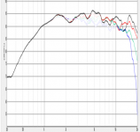
Hi!
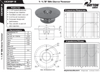
I'd say the peak comes from the driver itself. If I simulate it without any crossover it shows the same peak. Further, if I were the to scale the original Dayton plot to the same X- and Y axis as the simulation, it reveals the peak is present there as well.
I'd say the peak comes from the driver itself. If I simulate it without any crossover it shows the same peak. Further, if I were the to scale the original Dayton plot to the same X- and Y axis as the simulation, it reveals the peak is present there as well.
Attachments
- Status
- Not open for further replies.
- Home
- Loudspeakers
- Multi-Way
- My first crossover