Hi,
I've read, and read, and... well, yes read a lot about DIY crossovers.
Finally I reached my solution.
I just need some advice and/or recommendations to change anything that I'm not doing right.
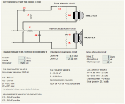
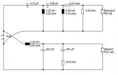
Here you have all the data and the diagram (in attach) I'm using to build my crossover:
TWEETER - MONACOR DT99:
Impedance (Z) 8Ω
Resonant frequency (fs) 1,500Hz
Max. frequency range fx-18,000Hz
Rec. crossover freq. (12dB) 2,500Hz
Music power 80WMAX
Power rating 40WRMS
SPL (1W/1m) 93dB
WOOFER: DAYTON
DC160-8 6-1/2" Classic Woofer 8 Ohm
Nominal Diameter 6.50"
Power Handling (RMS) 50 watts
Power Handling (max) 100 watts
Impedance 8 ohms
Sensitivity 88 dB @ 1W/1m
Frequency Response 30 - 4,000 Hz
Voice Coil Diameter 35 mm
DC Resistance (Re) 6.7 ohms
Voice Coil Inductance (Le) 2.34 mH
Resonant Frequency (Fs) 34.3 Hz
Mechanical Q (Qms) 3.47
Electromagnetic Q (Qes) 0.36
Total Q (Qts) 0.33
Many thanks in advance for any advice.
Ben
I've read, and read, and... well, yes read a lot about DIY crossovers.
Finally I reached my solution.
I just need some advice and/or recommendations to change anything that I'm not doing right.
Here you have all the data and the diagram (in attach) I'm using to build my crossover:
TWEETER - MONACOR DT99:
Impedance (Z) 8Ω
Resonant frequency (fs) 1,500Hz
Max. frequency range fx-18,000Hz
Rec. crossover freq. (12dB) 2,500Hz
Music power 80WMAX
Power rating 40WRMS
SPL (1W/1m) 93dB
WOOFER: DAYTON
DC160-8 6-1/2" Classic Woofer 8 Ohm
Nominal Diameter 6.50"
Power Handling (RMS) 50 watts
Power Handling (max) 100 watts
Impedance 8 ohms
Sensitivity 88 dB @ 1W/1m
Frequency Response 30 - 4,000 Hz
Voice Coil Diameter 35 mm
DC Resistance (Re) 6.7 ohms
Voice Coil Inductance (Le) 2.34 mH
Resonant Frequency (Fs) 34.3 Hz
Mechanical Q (Qms) 3.47
Electromagnetic Q (Qes) 0.36
Total Q (Qts) 0.33
Many thanks in advance for any advice.
Ben
Attachments
There are some questions: On what ground did you choose those drivers? What enclosure do you intend to build? How did you come up with the values of the attenuator circuit? Have you made any simulations? Do you have measuring equipment? Without the latter, you will hardly be able to design a proper crossover.I just need some advice and/or recommendations to change anything that I'm not doing right.
Here you have all the data and the diagram (in attach) I'm using to build my crossover:
Hi,
Its a general disaster area. That calculator is totally real world wrong.
With that bass unit build this :https://sites.google.com/site/undefinition/classix-ii
rgds, sreten.
At the price you can't go wrong with : http://gr-research.com/x-lsclassickit.aspx
Its a general disaster area. That calculator is totally real world wrong.
With that bass unit build this :https://sites.google.com/site/undefinition/classix-ii
rgds, sreten.
At the price you can't go wrong with : http://gr-research.com/x-lsclassickit.aspx
Last edited:
Hi,
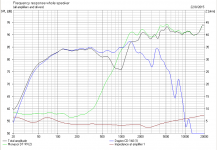
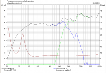
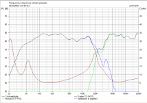
I made a quick and dirty simulation in 10 l (0.35 cuft) vented enclosure tuned to 42 Hz… it does not look too good, to say the least.
First simulation is without crossover, second with your crossover. At first glance I would say, those drivers do not fit together very well and the crossover erm… needs some improvements.
If this is your very first DIY project, I'd suggest you build a proven design before you start designing your own speakers.
Attachments
Why don't you just increase the tweeter attenuation to 5dB since the treble is 93dB and the bass is 88dB? C and R on the woofer circuit [the zobel network] do nothing useful and could be left off. With more thought I would leave them in as the bass seems a high inductance and the impedance will be rising at 2500Hz
Last edited:
Hi,
At risk of being left field, the best crossover is not to have one.
The DC160-8 should be run without a crossover and then you just match the DT-99 to intersect its frequency response.
If we work on 4 kHz at 80 dB and roll the DT-99 off to match 4kHz at 80 dB the combined output is then +3 dB at 4kHz.
If we now scale the DT-99 frequency response up using a first order crossover, for 80 dB at 4 kHz the DT-99 has to be -14dB.
Using 6 dB per octave the -9 dB point is 8 kHz and the -3dB point is 16 kHz, requiring a 1.1 uF capacitor, since the impedance looks to be 9 ohms. Easiest to use a 1uF capacitor as a nearest fit.
You now have a response that is 83 dB/W +/- 3dB from 45 Hz to 8 kHz and then a slightly rising treble to 92 dB/W at 16 kHz, which you can loose by listening slightly off axis.
Use a film 1uF capacitor and by pass it with a 0.01 uF Polypropylene Cap.
Almost no crossover.
Use a sealed box and play with the stuffing for best vocals, use radio or speech rather than singing, as your hearing is tuned to spoken voices.
Don't forget to use twisted cable inside the cabinet of at least 42/0.2mm.
Should be blinding, have fun.
Woa... impressive.
Many thanks to all of you for the fantastic input.
Ok, I'm going to start by answering some questions.
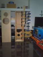
I did base my cabinets on the "Classix II" by Paul Carmody.
I made them taller (like you can see in the attached images) but the cabinet inside volume/liters were absolutely respected and I used the vent port suggested by the author (It is tuned to 40 Hz, which means you'll need a 1.5" dia vent, approximately 4" long.)
Why did I choose these drivers?
Because I had them from a previous buy (to replace old 6 1/2" speakers) and the DT99 where offered.
I also bought two "DC28F-8" Silk Dome Tweeter 8 Ohm
PRODUCT SPECIFICATIONS
Speaker Type Tweeter
Nominal Diameter 1.125"
Power Handling (RMS) 50 watts
Power Handling (max) 100 watts
Impedance 8 ohms
Sensitivity 89 dB @ 1W/1m
Frequency Response 1,300 - 20,000 Hz
Voice Coil Diameter 29 mm
DC Resistance (Re) 5.5 ohms
Voice Coil Inductance (Le) 0.09 mH
Resonant Frequency (Fs) 637.2 Hz
Mechanical Q (Qms) 0.82
Electromagnetic Q (Qes) 0.90
Total Q (Qts) 0.43
Surface Area Of Cone (Sd) 6.6 cm²
So, that's why I ended up with four "DC160-8" and two "DT99" and more two "DC28F-8" twitters.
Lots of drivers to let them get dust in the shelf.
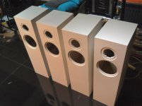
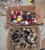
This lead me to assemble two different pairs of speakers. (see cabinet photos)
For one pair, I used two "DC160" and two "DC28F-8" twitters.
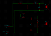
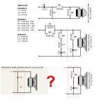
To this one, I assembled a specific crossovers based on the schematics by
Dennis Murphy "http://murphyblaster.com/content.php?f=main.html".
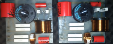
(See attached crossover schematics and photos)
Unfortunately, I must have done something wrong because the tweeters were almost inaudible with these crossovers.
I then decided to removed the L-Pad (R1+R2) and I could hear all the high frequencies back, but something stills sounding very wrong.
I even switch the tweeter polarity to check the inverted phase issue but to no avail. Well, it seems I really need to review it all. (start from fresh).
So, I decided to try new crossovers for the other speakers pair.
The one that uses the "DC160" and the "DT99" drivers.
That's why I used the free calculators available on-line but judging by your opinions, it seems I'm not going very far this way, either.
I don't have any software to test the drivers because I wouldn't know how to.
I downloaded this spread-sheet "http://audio.claub.net/software/jbabgy/PCD.html", but I must confess, I feel like a donkey looking to a palace. I wouldn't know where to start.
With all your input (that I truly appreciate) I feel even more lost, to the point where I'm considering to setup the most simple solution. Instead of a 2nd order -12dB per octave crossover, I guess I need to start by testing the most basic 1st order Butterworth. unless some of you (good souls) decided to help to design something that works for these drivers configuration.
Many thanks to all of you for the fantastic input.
Ok, I'm going to start by answering some questions.
I did base my cabinets on the "Classix II" by Paul Carmody.
I made them taller (like you can see in the attached images) but the cabinet inside volume/liters were absolutely respected and I used the vent port suggested by the author (It is tuned to 40 Hz, which means you'll need a 1.5" dia vent, approximately 4" long.)
Why did I choose these drivers?
Because I had them from a previous buy (to replace old 6 1/2" speakers) and the DT99 where offered.
I also bought two "DC28F-8" Silk Dome Tweeter 8 Ohm
PRODUCT SPECIFICATIONS
Speaker Type Tweeter
Nominal Diameter 1.125"
Power Handling (RMS) 50 watts
Power Handling (max) 100 watts
Impedance 8 ohms
Sensitivity 89 dB @ 1W/1m
Frequency Response 1,300 - 20,000 Hz
Voice Coil Diameter 29 mm
DC Resistance (Re) 5.5 ohms
Voice Coil Inductance (Le) 0.09 mH
Resonant Frequency (Fs) 637.2 Hz
Mechanical Q (Qms) 0.82
Electromagnetic Q (Qes) 0.90
Total Q (Qts) 0.43
Surface Area Of Cone (Sd) 6.6 cm²
So, that's why I ended up with four "DC160-8" and two "DT99" and more two "DC28F-8" twitters.
Lots of drivers to let them get dust in the shelf.
This lead me to assemble two different pairs of speakers. (see cabinet photos)
For one pair, I used two "DC160" and two "DC28F-8" twitters.
To this one, I assembled a specific crossovers based on the schematics by
Dennis Murphy "http://murphyblaster.com/content.php?f=main.html".
(See attached crossover schematics and photos)
Unfortunately, I must have done something wrong because the tweeters were almost inaudible with these crossovers.
I then decided to removed the L-Pad (R1+R2) and I could hear all the high frequencies back, but something stills sounding very wrong.
I even switch the tweeter polarity to check the inverted phase issue but to no avail. Well, it seems I really need to review it all. (start from fresh).
So, I decided to try new crossovers for the other speakers pair.
The one that uses the "DC160" and the "DT99" drivers.
That's why I used the free calculators available on-line but judging by your opinions, it seems I'm not going very far this way, either.
I don't have any software to test the drivers because I wouldn't know how to.
I downloaded this spread-sheet "http://audio.claub.net/software/jbabgy/PCD.html", but I must confess, I feel like a donkey looking to a palace. I wouldn't know where to start.
With all your input (that I truly appreciate) I feel even more lost, to the point where I'm considering to setup the most simple solution. Instead of a 2nd order -12dB per octave crossover, I guess I need to start by testing the most basic 1st order Butterworth.
unless some of you (good souls) decided to help to design something that works for these drivers configuration.Attachments
I think arturo has a reasonable idea about just high pass filtering the tweeter, but if the tweeter is 93dB versus about 85dB I think you could still use an attenuator [R1 and R2 in the calculator] You are right that you usually reverse the wiring to either bass or treble with a 2nd order, but you need to try it both ways, because the drivers are not flat at xover. That xover calculator is just a standard textbook filter and looks fine to me, perhaps with the switched tweeter polarity to avoid a notch.
If you do try that calculator, I was wrong with what I said - you have to keep C and R because the woofer is an ugly high inductance. Thats the trouble with guesstimating..
If you do try that calculator, I was wrong with what I said - you have to keep C and R because the woofer is an ugly high inductance. Thats the trouble with guesstimating..
Hi!
As you can see from my first simulation without crossovers, the DC160 is not much of use above 1500 Hz (IMHO).The DC160-8 should be run without a crossover and then you just match the DT-99 to intersect its frequency response.
Hi!
As long as you keep the baffle (outer) width too, which you did AFAICS, that is fine.I did base my cabinets on the "Classix II" by Paul Carmody. I made them taller (like you can see in the attached images) but the cabinet inside volume/liters were absolutely respected
I see.Why did I choose these drivers?
Because I had them from a previous buy (to replace old 6 1/2" speakers) and the DT99 where offered.
Maybe I'm missing your point, but why exactly didn't you start based on Paul's crossover, which at least matches your enclosure and woofer?So, I decided to try new crossovers for the other speakers pair.
The one that uses the "DC160" and the "DT99" drivers.
That's why I used the free calculators available on-line but judging by your opinions, it seems I'm not going very far this way, either.
Forget about testing the drivers for now, start with simulating the crossover design. I made a new simulation in Boxsim with your drivers and your enclosure, but with Paul's original crossover (which of course is not meant for the DT99). If you are up to it, download Boxsim (free) and unzip the attached file. That will give you a nice starting point to play around and see how different values of the crossover parts affect the frequency response. Boxsim might look a bit overwhelming if you never did simulations before, but actually it's quite simple, once you understood the basic concept. If any questions, feel free to ask. (Please note: It's just a simulation, reality will differ)I don't have any software to test the drivers because I wouldn't know how to.
Attachments
I think arturo has a reasonable idea about just high pass filtering the tweeter, ... If you do try that calculator, I was wrong with what I said - you have to keep C and R because the woofer is an ugly high inductance. Thats the trouble with guesstimating..
Many thanks "arturo" and "bigbottom" for encourage this simple approach.
Most of the time, the simple things are the best solutions.
I'll try it for tests, yet, I'm convinced that I would benefit from adding an inductor to the woofer circuit to cut all high end frequencies (at least all above 2500Hz).
See it as a driver protection.
I don't like to add much pressure on things.
I prefer to extend usability/life of stuff. (If I'm not saying any nonsense, that is)
Of course, the Zobel circuit is a must for this driver, I guess.
@Thusker,
After perform the above tests, (that I'm convinced it will develop into a 1st order Butterworth), I guess I'll try to go further following your advice.
To answer your question why didn't I start with Paul's crossover, it was because I emailed him about the adjustments from the "Vifa" tweeter (he used for his crossover) to the "Dayton - DC28F-8" tweeter and he, gently and helpfully, pointed me to Dennis's crossover since it was designed to work with the "DC160-8" Woofer and the "DC28F-8" tweeter, but yeah... I'm not sure why, it did not worked as expected for me.
Maybe I should have done just that. Start with Paul's crossover and try to adapt it for the the "DC28F-8" tweeter based on Denis's crossover, but, then again, the tweeter part of Dennis,s crossover was the one that did not work well.
Oh well, we learn making mistakes.
Yet, there is something I don't quite understand on the "Zobel circuits" in cause.
If you see Denis crossover scheme (in attach) the 47uF condenser connects (one tip) directly to the ground line, meaning that, reading the circuit from a positive to negative point of view, first comes the resistor and then the capacitor, yet with the free calculator, the signal flows the other way around. Again, reading from positive to negative, first comes the condenser and only then the resistor. Any logic explanation?
Is this any kind of mistake?
Many thanks.
Attachments
If it's CR or RC across the speaker they both look the same to the xover because the current flows through both in that branch.
At 423Hz the 47u capacitor is 8 'capacitor' ohms. These are not identical to resistance but as you go higher the cap impedance fades below the 8 ohms in the resistor giving a flatter impedance load to the filter since the driver impedance is rising..
Below 422Hz the 47u cap blocks current so that the xover doesnt meet BOTH ~8ohms from the driver and the resistor which could move the tuning and waste amp power.
If it's CR or RC across the speaker they both look the same to the xover because the current flows through both in that branch.
At 423Hz the 47u capacitor is 8 'capacitor' ohms. These are not identical to resistance but as you go higher the cap impedance fades below the 8 ohms in the resistor giving a flatter impedance load to the filter since the driver impedance is rising..
Below 422Hz the 47u cap blocks current so that the xover doesnt meet BOTH ~8ohms from the driver and the resistor which could move the tuning and waste amp power.
Ahhh... makes sense. Thank you very much for explaining it.
@tusker
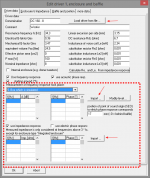
I'm playing around with Boxsim but I can't find the values (data sheet) to the DC160-8 nor the DT-99 drivers.
Here did you got those values for fill those fields, on the tests you presented? (see image)
Attachments
I downloaded this spread-sheet "http://audio.claub.net/software/jbabgy/PCD.html", but I must confess, I feel like a donkey looking to a palace. I wouldn't know where to start.
Ben, it looks to me like you are deep enough into this hobby that you should do yourself a favor and take the next step to learn a proper method of simulation. Accuracy may not be perfect but it can be surprisingly spot-on if you use the right tools.
Personally, I would stick with PCD. It's a very powerful and accurate piece of software. But what you need is some help using it. Try the following:
Tips-Volume-1-The-setup!!
Tips-Volume 2-Some-optimization-criteria
Tips-Volume-3
But start here before PCD:
https://sites.google.com/site/undefinition/simulated-measurements
or using slightly different programs:
FRD Consortium tools guide
http://audio.claub.net/Simple%20Loudspeaker%20Design%20ver2.pdf
And you may find The Speaker Building Bible helpful as well, although there are now some dead links here and there.
My Boxsim file already contains imported FRD and ZMA data, it's plug&play.I found the data sheets for the Dayton drivers on the manufacture site. Unfortunately Monacor seems to not provide a data sheet to the DT-99. :-(
You don't need to redefine the drivers, keep that step for later.However, I found the data for the DT-99 (and many more) here (dl the LASIP file of 'Ausgabe 7'); the Dayton data can be downloaded from the Dayton homepage. Just entering the T/SP will not give you a useful simulation, you need to import FRD and ZMA data. The best best way however would be to make your own measurements in the actual enclosure, but for now the web data will suffice.
This is how I do it. Eventually you find the right combination.
Ah... ah... yeah. It is a way of doing it, alright.
My Boxsim file already contains imported FRD and ZMA data, it's plug&play. You don't need to redefine the drivers, keep that step for later.
However, I found the data for the DT-99 (and many more) here (dl the LASIP file of 'Ausgabe 7');
Fantastic. Many thanks tusker.
Ben, it looks to me like you are deep enough into this hobby that you should do yourself a favor and take the next step to learn a proper method of simulation. Accuracy may not be perfect but it can be surprisingly spot-on if you use the right tools.
It won't hurt to read a little more about this issue and try other options, jReave.
The only risk I run into is to become an expert on the subject.

Again, many thanks to all of you.
You guys have been super.
All the best.
- Status
- This old topic is closed. If you want to reopen this topic, contact a moderator using the "Report Post" button.
- Home
- Loudspeakers
- Multi-Way
- My first crossover