Hi TVR try BAV21 for baker diode. Attached is model from NXP.
AndrewT have you experimented to see how the above diode affects the current in Q10 when VAS comes into saturation.
Regards
Will do. Thanks. I was thinking, as it is in parallel with the compensation, C is not important, so I should look for an ultra low leakage part even if it has high capacitance.
In the model, it works like the WIKI says. I can see it start to conduct as I creep up the input approaching clipping. I just don't understand the noise and distortion.
But if diode has high C then it Will increase thd, its to be expected, thats the reason to use a fast diode there.
I am a bit confused here. It can't be only the C as it is small compared to the compensation it is in parallel with. I have been looking into how the diode models work, so to understand it better I think I need to step some internal values. Much more to follow.
I can see the attraction of building an amplifier "obviously big enough" that you never get into trouble until the silicon fuses blow. We also have the decision that says, does it matter if it models at .004 with or .0006 without? All things to understand. A great amp is not my goal. Understanding how and why is.
I can see the attraction of building an amplifier "obviously big enough" that you never get into trouble until the silicon fuses blow. We also have the decision that says, does it matter if it models at .004 with or .0006 without? All things to understand. A great amp is not my goal. Understanding how and why is.
Made some progress. Tweaked a lot of details. I have not yet attacked current limiting on the outputs. I know this is a very simple somewhat classical and unimaginative topology, but it does model with .0001% THD @ 10K, -136 dB SNR. If reality was only 10 times worse, that would be pretty nifty. The worlds greatest amp is not my goal. This is educational. I think I have selected reasonably correct transistors that are available.
The red LED is a WAG. I expect my models are lying to me, but is comes out much lower noise.
The red LED is a WAG. I expect my models are lying to me, but is comes out much lower noise.
Attachments
Stability is part of protection, so I will ask about this here. It is my understanding that we must keep the phase shift between the output and input, or really between the bases of the input pair, to be less that 45 degrees at least until gain has dropped to zero.
So, I go to my simulation in SPICE and it kindly plots phase for these two points for me with the AC analysis. By this measurement, I am fine. But when I put a square wave in (injecting after the input filter) I get instability.
What am I not understanding here? Also, I have not figured out the plot calculation syntax to get it to subtract one phase from the other.
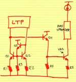
For D3 and D4 use BAS45a, which has very low reverse current. Spice Model below. Across C3 place two diodes in series, that somewhat reduces distortion. Across R1 you could add a speed up capacitor (its value is always a compromise) but it's not necessary. For drivers I'm usually using 2sa1930/c5171.
cheers,
*
.MODEL BAS45A D
+ IS=7.0000E-9
+ N=2.2707
+ RS=1.0000E-3
+ IKF=22.121
+ CJO=2.9332E-12
+ M=.24677
+ VJ=.3905
+ ISR=10.010E-21
+ NR=4.9950
+ BV=225.36
+ IBV=10
+ TT=1.7500E-6
.ENDS
**
cheers,
*
.MODEL BAS45A D
+ IS=7.0000E-9
+ N=2.2707
+ RS=1.0000E-3
+ IKF=22.121
+ CJO=2.9332E-12
+ M=.24677
+ VJ=.3905
+ ISR=10.010E-21
+ NR=4.9950
+ BV=225.36
+ IBV=10
+ TT=1.7500E-6
.ENDS
**
Playing with stability (200K in, 2 Ohm load) I found I needed .05u across R1 anyway, and had to hang 150p off the emitter of Q8. This was more stable than the network across the input stage.
It looks to me like the diode across C3 is an after the fact protection, so I did not include it. Provided I understand that correctly, reasonable. The diode across the IPS current mirror seemed to cause stability issues, so again, performance over protection. I seem to be at a point where for this basic topology, everything I do makes it simulate worse.
Is trimming R10 for perfect balance SOP? I have never seen any mention of doing this. Seems reasonable to me unless it does something bad I don't understand. Of course, it would be trimmed in the real circuit, real transistors and warmed up.
I tried a separate CCS for the VAS, and it's impact was in the .0000-something, so not worth the effort. I want to get the last couple of magazines from Jan as there is something about better bias stabilization in them. His WEB was having issues translating euro to dollars yesterday.
BAS45a, did not know that one. Looks good. I will for sure compare your driver selection with my latest guess.
Other crazy ideas:
As I have R19 and 68 in there anyway, I see no harm in putting some MOSFETS in the low side supply rails controlled by the TBD DC/thermal sensing. My thought is they could be fast enough to protect the first stages in case of a big output fault. This would let me put the output fuse inside the feedback loop as in case it blew, I would shut down the IPS and VAS before it blew up. I could even put in a comparator across the output fuse. In theory.
Attachments
I would also separate the CCSs. Have a separate one for input stage and one for VAS.
Here's something to try...
Try adding some shunt compensation to VAS output and move C5 take off point too the driver output.
Here's something to try...
Try adding some shunt compensation to VAS output and move C5 take off point too the driver output.
Sure will, later in the day when I get to the computer that has it on it.
I use several transistor models that are not in the normal library, most are from Bob, Central Transistor or Toshiba, but I am not sure about all of them which is why I did not put it out there. I merge my model files and as Spice removes all comments like copyrights when it does an update, posting my transistor file is not appropriate.
I am not positive about my methods of determining stability, which is a big part of the point.
Originally I had a copy where I bypasses the input filter and bypassed the feedback LF cap, putting a square wave of 1ns rise time in. I figure that has all frequencies and should excite anything. When the square was clean, it should be stable. Trial and error. I do it with 8 Ohms and 2 Ohms output. I am not using a complex load model. I probably should come up with one.
Next I tried to look at the Bode plots ( AC sweep 1K to 500K) and compare the phase across the input pair looking to see the margin below when the output crossed zero gain. Then, do things that I can calculate and see directly. If under about 45 degrees, it should be solid. This got me confused as what looked good here did not pass the first test. Copied schematics did not always pass this either.
So, I then went back to transient analysis and pit in 200K. When the output is visually clean, I am hoping it is good.
Loading the VS with more than 50p or so does not sound like a good idea, but this was about the only thing that brought the amps BW down. I am not sure it is real, as I have a hard time believing I came up with an amp capable of being an AM broadcast transmitter. I tend to believe rational thinking before the simulation. When I went to the faster inputs, it got harder to stabilize but distortion came down.
So, I have little confidence in the ways I am simulating this. I should build a complex load for the simulation and the bench. I only have real speakers and an 2-4-8 Ohm wire wound load. I used the load to fix the stability of my Hafler and it has worked in my office for a year just fine. Exicon Mosfets, so reality and simulation were never going to be quite the same.
Duh, I just thought. I should put n a LT op-amp simple circuit and compare the Bode plot with their recommended compensation examples. That might help verify my three methods.
No, standard operating procedure is to design a perfectly balanced current mirror with base current compensation -- including the output current, namely, the base current of the VAS emitter follower.Is trimming R10 for perfect balance SOP? I have never seen any mention of doing this. Seems reasonable to me unless it does something bad I don't understand. Of course, it would be trimmed in the real circuit, real transistors and warmed up.
Per Samuel Groner (Comments on Audio Power Amplifier Design Handbook, Section 3, "Improved Current Mirrors"), standard operating procedure would have you make 3 changes
- Install an emitter follower (Q3) to supply base current of mirror devices Q1 + Q2
- Set Ie1=Ie2 by choosing R1==R2 (within 0.5%)
- Set Ib3=Ib4 by choosing R3==R4 (within 0.5%)
By the way, the famous 741 opamp IC used exactly this input mirror + buffered VAS, in the late 1960's. Have a look at its schematic. Q7-R3, Q15-R12.
Attachments

Last edited:
Here is my model.
I tried a few "improved" mirrors, and contrary to expectations, they did not seem to work well. As I will only be able to match the inputs so well, I figure adjustment is actually the best practice. Pot on the bench, then solder in the resultant value.
I tried a few "improved" mirrors, and contrary to expectations, they did not seem to work well. As I will only be able to match the inputs so well, I figure adjustment is actually the best practice. Pot on the bench, then solder in the resultant value.
Attachments
Mark,
I see your SOP. Makes sense and I will play with that, but it is too large a topology change for this effort. Still, one is dealing with only so close matching of the inputs. Some trim would still be needed. I have seen Q3 used to blink an clipping indicator as a secondary function.
I have R2 at about 100 Ohms, so that is very much in line with your thoughts.
BAS45 made a substantial improvement. I also found actual models for the 1N4007. .0037% @ 20K. Seems this diode is good enough to sprinkle around. I should go get a handfull for my Hafler.
I tired separate ccs's, and it did not make any real change. I suspect the VAS is just not as sensitive. C14 is a VAS shunt, but to ground, not the negative rail. I fount it far more effective the way I installed it.
I payed with output inclusive compensation and found it made for very solid oscillators. The TMS seems to be the slick ticket.
On to the obvious layers of protection, thermal, DC and shorted outputs.
Here is my crazy idea. I put some low R MOSFETS in the supply rails for the IPS and VAS. So, when there is a fault, I shut down the first two stages nice and fast. That means I could put that noisy fuse for the speakers inside the feedback loop without fear. If I did have an output failure, maybe I would not kill half of the VAS as is sometimes the case. Normal sensing for thermal and DC overload, and even putting a comparator across all of the fuses, supply and output, to shut down the input stages quickly while the normal output mute relay drops and the main supply bleeds off. Or, is it just as smart to just drop in a FET switch to short across the input stage.
This needs a separate small supply, so of course, that leads to the slippery slope of "might as well" as might as well make it high voltage and regulate the IPS and VAS power while I am at it. Sigh, not this time 🙂
BAS45 made a substantial improvement. I also found actual models for the 1N4007. .0037% @ 20K. Seems this diode is good enough to sprinkle around. I should go get a handfull for my Hafler.
I tired separate ccs's, and it did not make any real change. I suspect the VAS is just not as sensitive. C14 is a VAS shunt, but to ground, not the negative rail. I fount it far more effective the way I installed it.
I payed with output inclusive compensation and found it made for very solid oscillators. The TMS seems to be the slick ticket.
Remember you are in the sim world. In real life separate CCSs may make a difference.
Have you tried just including the drivers in the miller loop and not the whole OPS? You should be able to use the VAS shunt compensation to stabilise this loop. It does not matter whether this shunt goes to rail or 0v. There is no DC element.
Also, you may want to slow your amp down a little for first prototyping. Have looked at the stability using your latest .asc file. The ULGF looks a little high to me. I go for 1MHz or below then try to speed things up once you have a working prototype. The penalty for slowing the amp down is higher THD, the gains are all in the stability (Gain Margin, Phase Margin).
Last edited:
I hear ya on that. Much bigger VAS shunt for the power up day maybe. I have a big autotransformer, so I bring things up slow. When I started, I did not expect to have a multi-Mhz amplifier. In the SIM at least, It is very educational to see how the ultra wide bandwidth decreased IM so much. Some I knew, but I did not see clearly why 80K or so was not fully sufficient. It does matter at 5 to 7K what is going on at 100K. Wow.
My goal here is mostly to understand amplifier design, not so much make a great one. That is why I am not doing drastic topology changes. This result, though it looks surprisingly text book, was an evolution of changing everything until the tradeoffs lead me into this direction. I went through cascode inputs, full symmetrical, exotic ccs and current mirrors. I started trying to make current feedback pair output behave, but went back to EF. Adding the Darlington VAS was far more of an improvement that I could have imagined. The difference between it's collector connected to ground, not Q9's collector is also much larger than I expected. In my Hafler mod, the TMS did nothing because the VAS is not good enough. Here, outstanding. Just about every curent I have played with, selection of every transistor. Not that I have the best, but every change now seems to make it worse. "Reasonable" is how I choose to call this.
I am trying to understand some of the protection methods. This is a subject usually left totally un-addressed i schematics on the WEB or in Chinese kits. Modern amplifiers seem to spend a lot of time dealing with this. I guess the current market expects people to be so stupid, they have to or get sued. Most "classic" amps had no protection at all. Over in the lounge, many very experienced gentlemen have implied they have never heard a protection method that did not degrade the sound. My ears, or more correctly my secret weapon of my wife's increadable intolerance for distortion, is not THAT good.
I had a diode across C3. It seemed to do no harm, but I can only see it doing something in some special case, so I deleted it. Q17 seems to do no harm. I had a diode across B-C of Q6, but it caused stability issues. I only sort of see how it prevents the input from going too far. I should try the BS45 there. Everything I have tried from the white papers I have for output stage current limiting has been very bad for distortion. More work to do.
In some respects, is not the magic of the TMC that is is taken back to the output at it's center point, so it is including the output stage.
High on the learning list is to compare the sim world with reality. My experience it other modeling is that if you understand what the model is doing, you can translate that to the world. If you are just punching numbers, you miss the moon. Part of this voyage is to do the DC analysis by hand and compare it to the sim. I learned my electronics in tech school, not engineering, so it is a big step after all these years.
- Status
- Not open for further replies.
- Home
- Amplifiers
- Solid State
- My first amp, protection