Hers is the result of my studying prior art for the purpose of understanding amplifier design and what I learned about topology causing different amps to sound different on the same speakers. I originally had no intentions of building something, but now feel I probably should as SPICE leaves much to be learned with reality. So, I need to address some of the secondary issues. Clipping recovery or grasefullness and the like. I make no claims there is anythig groundbreaking here, just an attempt to design an adaquate small amp. ( I have a transformer and heat sinks, so that was my target).
Crazy idea: Use big MOSFET switches in the power supply rails for protection. They would be fast enough to protect the outputs and speakers without blowing fuses. Current or DC sense could be fast enough they could open together before the smoke is let out of the outputs. I would still need a conventional output relay for AC fault and turn on/off unless I did a separate set for the low power stages.
For any advice, please provide some "why" as this is mostly educational. If I wanted another good amp, I would just pull one of my spare Parasounds out.
Sorry about the red. Don't know why Printkey 2000 started doing that.
Attachments

Another thread had a hint to find Kiwanuka's paper on SOA. Just what I was looking for to start. Recovery is another issue.
Another thread had a hint to find Kiwanuka's paper on SOA. Just what I was looking for to start. Recovery is another issue.
Recovery - Baker clamp between VAS input and VAS output to prevent VAS saturation during clipping.
Thanks. Found it in WIKI (of course) . If using the single Shocttky diode implementation, any recommendation on a part? Or is a pair of 1N4148's more normal?
This is because coming out of saturation is slow and ugly, we apply negative feedback to kill the gain as we approach saturation?
This is because coming out of saturation is slow and ugly, we apply negative feedback to kill the gain as we approach saturation?
Only a beginner in this amplifier design game so some one more knowledgeable could better explain the precise mechanism.
All I know is the effects of using this diode and the results shown on a scope. I use a single 1N914 diode. Lower capacitance version of the 1N4148 and dirt cheap. Never tried a schottky.
All I know is the effects of using this diode and the results shown on a scope. I use a single 1N914 diode. Lower capacitance version of the 1N4148 and dirt cheap. Never tried a schottky.
Hmmm. A single diode? I thought it had to have a lower junction drop than the transistor. So Germanium or Schottky. As I understand it, as the transistor reaches saturation, it gets reduced base current and self regulates. One of the things I am learning is that what looks to be very simple may have three or four effects. If silicon, you would need the additional diode or two on the base.

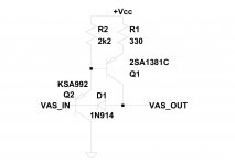
Ah, this is a slick trick. If it was a single transistor VAS, then you need two diodes or one with a lower drop. But with a buffered VAS, it should work. Nifty I think. I'll play with it in the model.
It's a fairly well known trick. Personally never use the beta enhanced VAS without one.
PS If you can get hold of the KSC3503 for the VAS output transistor it is highly likely you will get a more pleasing sound from the amp.
PS If you can get hold of the KSC3503 for the VAS output transistor it is highly likely you will get a more pleasing sound from the amp.
Thanks for the VAS tip. Looks like Mouser has them. I see one has a Cordell mode, the other I will type in. Glad to have some models of transistors still in production. Seems like a big device for the VAS considering my quiescent current is only 6 ma through the CCS, splitter and VAS. I am not well versed on what to look for in a transistor in each stage past it not getting fried. Just learning the other details.
6mA and +-40Vdc gives a quiescent dissipation of 240mW and a Vce0 > 80V.
If VAS needs 12mA quiescent and the amp is on +-50Vdc, then Pq~600mW
Both these are outside the capability of a 600mW To92 device.
If VAS needs 12mA quiescent and the amp is on +-50Vdc, then Pq~600mW
Both these are outside the capability of a 600mW To92 device.
Thanks for the VAS tip. Looks like Mouser has them. I see one has a Cordell mode, the other I will type in. Glad to have some models of transistors still in production. Seems like a big device for the VAS considering my quiescent current is only 6 ma through the CCS, splitter and VAS. I am not well versed on what to look for in a transistor in each stage past it not getting fried. Just learning the other details.
Mouser is where I got mine from.
Did an experiment using 2x 2n5551 in a beta enhanced VAS, 3 transistor cascode VAS (3x 2n5551) and the 2n5551/KSA3503 in beta enhanced VAS. All other circuit details stayed the same and the 2n5551/KSA3503 was just in another world. Next experiment is the KSC1845/KSA3503 beta enhanced VAS.
It may seem like a big device to use but it is a very special device. Just look at the Cob, for example. I have a VAS current of 3mA in current prototype and still use that pair (KSA1381/KSA3503). Even with the mismatched gain rankings they still win out.
The details that are involved in amp design are just mind boggling.
Modeled it with the larger VAS and drivers. Upped from 6 to 10mA VAS quiescent. Nice improvement. Changed to a double EF output. Slightly worse HD, but the crossover glitches are gone and it was much easier to stabilize. The Baker clamp in the VAS works, but it adds over 20dB of distortion and noise. I am not sure I understand why. It's leakage is that that bad and another 3p is not going to do much. I added a transistor to the VAS to prevent over-current at clipping. It seems to me that this transistor would serve the purpose of sucking the VAS base dry just as well.
For sure a "simple" amp is mind boggling.Good thing I lost my mind years ago playing with old British sports cars and designing speakers. Everything effects two or three things. There is no "right way". There are a lot of pretty good ways, and seems quite a few bad ways to do things. That's why it is so fun. On top of that, just learning how to use SPICE and know when it is lieing is no east task. Without the help of this forum, I could not take on this learning effort.
For sure a "simple" amp is mind boggling.Good thing I lost my mind years ago playing with old British sports cars and designing speakers. Everything effects two or three things. There is no "right way". There are a lot of pretty good ways, and seems quite a few bad ways to do things. That's why it is so fun. On top of that, just learning how to use SPICE and know when it is lieing is no east task. Without the help of this forum, I could not take on this learning effort.
Which diode model did you use for the VAS baker clamp?
Yep, there is no right way just your own way. That's the beauty of DIY Audio 🙂 Nothing beats warming up the soldering iron and just experimenting with different ideas.
Have you checked out the 2sa1930 / 2SC5171 (Mouser again) transistors?
Could you publish a schematic of your revised creation please?
Old British Sports Cars... 😀
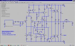
About 350mW for the VAS. Half a watt for the drivers. Up to 20v/us slew. I also dropped the gain slightly to an even 26dB "standard" by changing R8 to 510 and all the input degeneration to 100 Ohms. Bought a couple of dB lowered distortion.
Add a dissipation limiting resistor to the collector of Q10.
usually around 1k to 2k for a higher voltage amplifier.
I have seen quite a few recently at much lower values in lower voltage amplifiers.
So anywhere from 200r upwards.
Q17 will be into limiting region when VAS current reaches 18mA.
Could that be the source of your added distortion?
Split R22 to get more current before limiting starts.
What is the other end of D3 connected to?
- Status
- Not open for further replies.
- Home
- Amplifiers
- Solid State
- My first amp, protection