Vostro,
Not for stability, but to see the effect. Raised distortion dramatically. I should look at that again for stability. 10 Ohms is magic on tubes. Not sure on BJTs. It is going to lower the time constant due to Cob?
This is an interesting evolution. From textbook to real world, from .00000-something distortion in fantasy-land, to hoping the end result is less than .01.
A few clarifications.
Of course the bias would be adjustable. Fixed is only for simulation. Real world usually combines a fixed resistor to make the pot adjustment/drift less sensitive. You don't want it to fail on the low side and shoot the bias to 9 Amps. R10 would be hand selected at warm up for input balance. If the real world of output mis-matching has DC above a few mV, I will add a DC adjustment to the feedback line. Not needed in the model, needed in real world. I do hate pots as I never saw a good one. Unfortunately sometimes we must use them.
I have not shown any power supply. I understand them well. Not an issue. Likewise many books have been written on physical construction ( Jones on tubes was excellent) so I have not mentioned any of that here. Assume I actually know what I am doing in that area.
Bias: I really just picked something so I could readjust to the same point when I made changes. I had targeted 125mA bias as it seemed to be the lest distortion. I have been advised that it is better to err on the high side so as not to go too low when hot. I guess that is why 135 is a more common value.
From Self, I reduced the output emitter resistors to .1 from .22. I wonder if I am sacrificing stability as I can only match the outputs so well (or actually afford a big enough pile of them to select from). .22 seems to be an industry standard, It is wise to listen to "that's how we do it" but it is also wise to question it.
I need to run through the SOA of all the parts again. Listed are intentionally selected now, not convenient parts I had a model of as in my first postings. I don't yet have an arsenal of parts I know to throw at each use. For that I have been carefully listening to advice. I have used the 2n5551's as that was what was in my Hafler and I have 20 or so on he shelf. They functioned as small transistors to get me started. I stumbled onto the 2N5210's. They look better for this use, but I am sure there are many others. About half the time I find a reference, the part is OBE.
I have not gone through and caused intentional damage to see what the DC conditions are under fault. That's on my list. I found out the hard way that step was omitted on more than one amp I have fixed.
I have not a clue on issues like "rail sticking" or other issues of recovery as the models don't seem to deal with that. Clipping looks textbook clean and I know that is not true. That's why I am here.
ARGGGG. 2sc3503 is now listed as OBE.
Other recommendations on the medium power, VAS and drivers? 150V or better, several watts. TO-126 or something like that.
Other recommendations on the medium power, VAS and drivers? 150V or better, several watts. TO-126 or something like that.
OK, other versions still in production. Boy, not much out there with its specs.
Exactly, KSA versions are the same parts. Even with gain rank mis-match they take some beating.
Any thoughts on my crazy protection? Probably costs more that shotgunning all the active parts if a failure did happen, but it was an idea.
On to the obvious layers of protection, thermal, DC and shorted outputs.
Here is my crazy idea. I put some low R MOSFETS in the supply rails for the IPS and VAS. So, when there is a fault, I shut down the first two stages nice and fast. That means I could put that noisy fuse for the speakers inside the feedback loop without fear. If I did have an output failure, maybe I would not kill half of the VAS as is sometimes the case. Normal sensing for thermal and DC overload, and even putting a comparator across all of the fuses, supply and output, to shut down the input stages quickly while the normal output mute relay drops and the main supply bleeds off. Or, is it just as smart to just drop in a FET switch to short across the input stage.
This needs a separate small supply, so of course, that leads to the slippery slope of "might as well" as might as well make it high voltage and regulate the IPS and VAS power while I am at it. Sigh, not this time 🙂
Just thinking aloud here...
Not so crazy to use MOSFETs on the positive rail. You could use a photovoltaic mosfet driver. Removes the need to a floating extra supply.
I would consider using solid state relays (MOSFETS) on the power rails and amplifier output. Then you could use some very small resistances on the power rails and monitor them for overload. Then use this too completely shut down the whole amp until a manual reset.
Thermal overload is easy to integrate into this system.
You could leave the main transformer live during fault conditions and use this to derive the low voltage rails for the protection circuitry.
Making lots of progress understanding details with the patient help of those with far more experience have offered. Many thanks for the ongoing help and support through the PM channel. So much to learn. So much not in the books. Learning is my primary goal, so this is a very worthwhile project if I wind up with an amp or not.
The amp remains terribly conventional as I have tried to attack the biggest issues and not made otherwise valid improvements where they are not the main performance driver at that time. As an example, I see advantages of a cascode FET symmetrical IPS and VAS. Heck, I own four Parasounds, but it is clear to me the outputs are by far the limiting factor and my simpler LTP/Darlington VAS is better than the outputs. Please, keep comments coming. Just because I don't choose to go that way does not mean I was not listening. I have been resisting an output triple, but if I stay BJT, I may be forced there. Toshiba TTA/TTC series transistors for the drivers may be the fix if I can find them. Too new. I have one modeled with Lateral MOSFETS that also solves the output base current starvation. Which will be easier to do the bias compensation I am not sure. One 2Vbe, one 4Vbe. Here I think I have to put it on the bench to know and I am not ready for that. Which is easier to deal with at clipping I don't know either. The BJT comes out ahead in the linearity but not by enough to be a driving factor.
The last few days I made it as far as trying to do the SOA graphs.
Problem One: The graph provided by OnSemi is log, not lin. I guess I could re-plot it. Why on earth, if we need a linear plot, would they publish a log plot?
Two: I have no way to draw anything but the restive load line if I HAD a lin graph.
So: I modeled a dual slope IV system as per Mendenhall. I know others are better but I was starting slow to see how they work. GASP, and I thought I had issues with rail sticking!
Good news followed. I am using hefty paired outputs for a pretty small amp for performance reasons. It also means on the log plot from OnSemi, unless I feed a 20K sine wave at full power for over a second, with a blanket tossed over it, into a 2 Ohm load, and my bias servo doesn't work, I never reach secondary breakdown anyway or thermal limits. I fall into using the best sounding output IV limit there is. None. I will model more of these and play with them to understand them better, but knowing I don't need one makes me feel better about the result.
The transistor in front of the Darlington VAS works nicely on negative going peaks.
"Standard" placement of diodes on the input current mirror and the baker clamp across the VAS may limit, but do so very ugly. Glitches and ringing.
I see a great many of the glitches seem to show up and stress things I would not have guessed, like the ccs for the VAS. Nasty things show up on the feedback where I went to the trouble of getting a wide response, it now is a detriment.
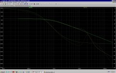
I am finally far more confident in stability modeling. Where I was going wrong is in not limiting the BW. Once I tamed (via an IPS shunt RC) it to under a meg, I could make the typical compensation changes and what I see in the Bode plots correlate with what happens when I send a 20K clipping level in. What goes on at 12 to 20 Meg is too much to deal with so now I don't. The end result actually models lower THD-9 with the faster small BJT's than the older slow ones running full BW.
Progress continues.
*I was going to look into the TA7317, but I see it only on e-bay. Obsolete? At a minimum I need basic DC and thermal overload, turn on delay and off mute. I have not copied any of the many versions until I know the conventional is the way to go.
*Looking at the Therma-Track outputs. Even bigger, and I can use one diode for bias comp, one for over-temp.
*Looking to see if any input clamp kluge would clip smoother. A little distortion at peak beats ugly glitches and rail sticking.
Here is the MOSFET driver version for your entertainment showing where I am right now. So much more to do. Independent ccs reference for the VAS seems to help clipping. Just a resistor is even better behaved but THD numbers goes up. I am afraid only building and listening will tell which is the "better" amp. I am not posting the .asc as I have integrated all my transistor models and it would not run without my libraries.
The amp remains terribly conventional as I have tried to attack the biggest issues and not made otherwise valid improvements where they are not the main performance driver at that time. As an example, I see advantages of a cascode FET symmetrical IPS and VAS. Heck, I own four Parasounds, but it is clear to me the outputs are by far the limiting factor and my simpler LTP/Darlington VAS is better than the outputs. Please, keep comments coming. Just because I don't choose to go that way does not mean I was not listening. I have been resisting an output triple, but if I stay BJT, I may be forced there. Toshiba TTA/TTC series transistors for the drivers may be the fix if I can find them. Too new. I have one modeled with Lateral MOSFETS that also solves the output base current starvation. Which will be easier to do the bias compensation I am not sure. One 2Vbe, one 4Vbe. Here I think I have to put it on the bench to know and I am not ready for that. Which is easier to deal with at clipping I don't know either. The BJT comes out ahead in the linearity but not by enough to be a driving factor.
The last few days I made it as far as trying to do the SOA graphs.
Problem One: The graph provided by OnSemi is log, not lin. I guess I could re-plot it. Why on earth, if we need a linear plot, would they publish a log plot?
Two: I have no way to draw anything but the restive load line if I HAD a lin graph.
So: I modeled a dual slope IV system as per Mendenhall. I know others are better but I was starting slow to see how they work. GASP, and I thought I had issues with rail sticking!
Good news followed. I am using hefty paired outputs for a pretty small amp for performance reasons. It also means on the log plot from OnSemi, unless I feed a 20K sine wave at full power for over a second, with a blanket tossed over it, into a 2 Ohm load, and my bias servo doesn't work, I never reach secondary breakdown anyway or thermal limits. I fall into using the best sounding output IV limit there is. None. I will model more of these and play with them to understand them better, but knowing I don't need one makes me feel better about the result.
The transistor in front of the Darlington VAS works nicely on negative going peaks.
"Standard" placement of diodes on the input current mirror and the baker clamp across the VAS may limit, but do so very ugly. Glitches and ringing.
I see a great many of the glitches seem to show up and stress things I would not have guessed, like the ccs for the VAS. Nasty things show up on the feedback where I went to the trouble of getting a wide response, it now is a detriment.
I am finally far more confident in stability modeling. Where I was going wrong is in not limiting the BW. Once I tamed (via an IPS shunt RC) it to under a meg, I could make the typical compensation changes and what I see in the Bode plots correlate with what happens when I send a 20K clipping level in. What goes on at 12 to 20 Meg is too much to deal with so now I don't. The end result actually models lower THD-9 with the faster small BJT's than the older slow ones running full BW.
Progress continues.
*I was going to look into the TA7317, but I see it only on e-bay. Obsolete? At a minimum I need basic DC and thermal overload, turn on delay and off mute. I have not copied any of the many versions until I know the conventional is the way to go.
*Looking at the Therma-Track outputs. Even bigger, and I can use one diode for bias comp, one for over-temp.
*Looking to see if any input clamp kluge would clip smoother. A little distortion at peak beats ugly glitches and rail sticking.
Here is the MOSFET driver version for your entertainment showing where I am right now. So much more to do. Independent ccs reference for the VAS seems to help clipping. Just a resistor is even better behaved but THD numbers goes up. I am afraid only building and listening will tell which is the "better" amp. I am not posting the .asc as I have integrated all my transistor models and it would not run without my libraries.
Attachments
Q17 just starting to turn on when the VAS current increases by ~8mA. Maybe that threshold should be a bit higher.
R17 seems unusually high. Only 180uA through Q10.
Q10 would benefit from a collector resistor, to protect it, if overloaded.
I wonder if R10 & R11 would be better if raised slightly.
The reason many show the SOA with log log scales is, so that many of the plots end up with straight lines.
Have you read David Eather yet?
If I add a Rc to Q10, it causes further instability. I don't really see the risk. Even at sat, the reduced R17 means only .4mA. To do that would mean something else has gone wrong and I would hope it causes shutdown first. Good enough for now.
Thought about higher R10 and 11. It would make matching errors easier, but again, pushing stability. They can go to 220 OK. Guess it is worth it for the real world. Same thing on R4 and 5. It seems happiest at about 100.
R17 does seem a tad high, but I am not seeing base starvation. Cut it to 2.2K and it did improve very slightly. I did not see that before, so it must have been masked by a bigger problem. ( I have fixed many).
It seems like everything I change causes stability issues at about 12M. All those secondary poles ganging up on me. Resisting slowing it down too much as distortion rises again and I don't seem to have mastered the art of the zero. Much much more to learn.
Added flying catch diodes across the bias servo. To do so I had to give up on the .1 Ohm output Re, but they just happen to work if the load goes to two and the input is clipping. ( 8A or so) so maybe a good start to delay blowing outputs or speakers until the speaker relay kicks in. (assume it will be there) Action is a bit ugly, but I look at these as a fail-safe. Better than a fuse I think.
If seriously overloaded, like 24V p-p which my preamp is happy to supply, it causes ugly things, so maybe I should do something on the inputs in the 5V range. ( +/- 1.7 being full power and it is happy with 4Vp-p.
More to look at Q17. As it is, it reduced what looks like a slight hysteresis coming off the neg rail with the accompanying glitch. I am also looking for better BJT drivers. The ones I found don't seem to be widely available yet, so I am intentionally limping along with 2sa1381/2ac3503 in the BJT version. I kept the VAS current the same between the two temporarily just to compare apples to oranges, not turnips. I want to double the VAS standing current and re-stabilize. Maybe Q17 would cause an issue then.
By happy or ugly, I am looking at currents all over the place while clipping at various loads, 8 down to 2 and restive load or Cordells generic speaker load. The further from a sine wave I see, the uglier I will call it. Glitch and ringing are bad. Very scientific eh?
I have not found much of anything on helping clipping recovery, especially rail sticking. I don't want to be too aggressive in input limiting, but which is the better of evils? The smoothest of course, but which is that?
Found uPC-1237's still around. NOS I guess. Working up the usual remote on, DC, AC, temp, mute, the old fashion way first. I have not read what fancy things Rod Elliot has with his PIC based board, but as this is more about how it works than how well, I should do it the hard way at least in Spice.
Afraid I missed something on David Eather. Can't find any reference besides things like Linkedin.
Real bummer is I am feeling much better and will crawl back to work tomorrow so that will crimp my play time. I tell you, what was a simple cold 10 years ago kicks me flat into bed now.
Just did a little research on CAD programs and downloaded DipTrace. The cost of small boards is a lot less than I thought leading me to more options than I would have considered, like some of the newer SMP small transistors and far more complex safety monitoring and control than I was willing to vector-board. Of course, that is yet another side-track to learn. The never ending hobby.
I hope you are deliriously happy with DipTrace, both now and in the future, and that it does everything you want, and that you find it shockingly easy to use. Intuitively obvious.
FYI, I chose the competitor product "KiCad" because (a) it's open source software; and (b) the full featured version with all the bells and whistles, the one that can lay out 256-layer boards sized 100 inches by 200 inches, costs zero. (Whereas the Big Brother edition of DipTrace costs $895). There are online KiCad tutorials, also for free.
DISCLAIMER: If/when you buy a copy of KiCad (for $0.00), I get a 15% commission. So don't consider me a disinterested third party. 😱 I've got a dog in this hunt.
Member
Joined 2009
Paid Member
good to see there are others out there who have the same goal as meLearning is my primary goal,
I like this, I may borrow some of these ideas some time - keep it going.Here is the MOSFET driver version for your entertainment showing where I am right now.
David Eather articles on SOA: manual calculation method
http://www.diyaudio.com/forums/solid-state/112317-understanding-output-stage-soa.html#post1357713
After further reading and experimentation I have changed my view on design target 2
2.) Look at driving a resistance equal to one third of your intended speaker impedance, i.e. a test/dummy resistance of 2r7 for an 8ohms speaker load.
http://www.diyaudio.com/forums/solid-state/112317-understanding-output-stage-soa.html#post1357713
After further reading and experimentation I have changed my view on design target 2
It now becomes:2.) Look at driving a resistance equal to half your intended speaker impedance.
2.) Look at driving a resistance equal to one third of your intended speaker impedance, i.e. a test/dummy resistance of 2r7 for an 8ohms speaker load.
Last edited:
It occurred to me that under clipping, the ugliest situation was the action of the diodes I put across the bias servo. They do their limit job well, but when they turn off, nasty glitches are everywhere. So I stuck in a model for a fast Schottky,(ZZLS1000) but I was really thinking about a HEXFRED like Vishay VSFA042D60S or something after how well they have worked for me as rectifiers. By SPICE, this works like a charm. Any recommendations on this? (Vishay did not have a model). About time to do the delay/temp/AC stuff.
Most of my progress is in reading and trying things that don't work. Went for 4A over the 1A diodes on the output for example. Added placeholders for a lot of parts I may not need, but should be in the PWB like bass stoppers, DC offset adjustment etc. Constant current sources are completely split and are feedback pairs.Yes, a cascode JFET is stiffer, but in the VAS you run out of headroom. Separated the references as it seems to help keep clipping recovery cleaner. I will have a mute relay, so I am not concerned with turn on thump.
Most of my progress is in reading and trying things that don't work. Went for 4A over the 1A diodes on the output for example. Added placeholders for a lot of parts I may not need, but should be in the PWB like bass stoppers, DC offset adjustment etc. Constant current sources are completely split and are feedback pairs.Yes, a cascode JFET is stiffer, but in the VAS you run out of headroom. Separated the references as it seems to help keep clipping recovery cleaner. I will have a mute relay, so I am not concerned with turn on thump.
Taking the easy way out on the easy stuff. The ESP project 33 provides the basic mute and DC sense ( pretty much the Self circuit I was going to use). I will just use snap-switches for the heat sinks, fuses for the rectifiers and rails. This part I understand. I actually need to add it to 3 amplifiers.
Guess I need to wait for issue 7 of Linear Audio for a more complete description of Tian probe to look at stability from another, hopefully more precise, angle.
Here is the current all BJT version and a list of what kept me busy for a few days.
Unless there is something dramatic I missed, line that has never happened before, this is getting close to what I will build. Either the BJT or MOSFET drivers. I have most of the parts to mock up enough to work out the bias servo on the real heat sinks using the Chinese boards I bought. I still believe there is more to be gained there not only in control, but in threshold detection and protection. For an amp this small, probably not worth the effort.
I am off to understand the board layout software.
Attachments
- Status
- Not open for further replies.
- Home
- Amplifiers
- Solid State
- My first amp, protection