Or a $39 Variac, which will allow you to also fire up finished amplifiers.
http://www.mpja.com/Transformers-Power/products/45/
http://www.mpja.com/Transformers-Power/products/45/
Power supply!
Would like to ask a little but important question.
Have started to put the last things in place on my Aleph P1.7 boards and realized that I had forgot about the additional power supplies for the relays and later also the volume control. Thing is that I need 5 volt for the relays and 15 volt for the volume control from Jims Audio.
Question is should I get another torodial trafo with 2x18 volt and bring it down from there or go for two smaller trafos with 9 and 18 Volt instead?
Can someone help me to figure out how to calculate the power loss for the 5 volt regulator cause that is the one who have to dissipate moste power.
I intended to just use regulators type 7805 and 7815 for the regulation with some minor cap (220-1000 uF) before and even smaller after the regulator. Will that be ok or I should go for more filter... since it will only be for relays and volume control?
I have no problem with space and I even think I have space enough to shield the incoming power from the signals as good as it is possible.
I´ll come back with pictures in the evening.
Hi TIC37,
One thing to point out is that depending on how much capacitance
after the regulator you may want to add a protection diode. For
example, see p.13, 8.1.1 and Fig 15 here:
http://www.ti.com/lit/ds/symlink/lm7815.pdf
Cheers,
Dennis
One thing to point out is that depending on how much capacitance
after the regulator you may want to add a protection diode. For
example, see p.13, 8.1.1 and Fig 15 here:
http://www.ti.com/lit/ds/symlink/lm7815.pdf
Cheers,
Dennis
On the road again!
The boards for the Aleph P1.7 are ready and they turned out nice I think, function will be tested during the week but from what I can see everthing should be ok, no shorts, no cold soldering from what can be traced by my eye.😉
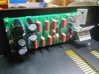
Have started thinking about layout in the chassie and I am a little dissapointed cause the chassie I have bought from Toroidy.pl is Ok but they have taken up a hole for the IEC and I don't want it in the corner.... I want it in the middle🙁!!!
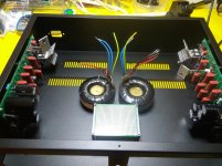
This is the thought layout cause this way I can isolate incoming AC, internal DC and signal wires so that I can also shield the transformers and keep things out of the way, any ideas.
I have thought that I will put both volume control and eventual incoming signal board furthest back so I keep them together with signals but I still havn't checked the size so that I have to do before I start taking up holes, but I will get it working....🙂
I am going to put it up with an ordinary selector for the moment but later I will have a relay controlled signal board also.
The boards for the Aleph P1.7 are ready and they turned out nice I think, function will be tested during the week but from what I can see everthing should be ok, no shorts, no cold soldering from what can be traced by my eye.😉

Have started thinking about layout in the chassie and I am a little dissapointed cause the chassie I have bought from Toroidy.pl is Ok but they have taken up a hole for the IEC and I don't want it in the corner.... I want it in the middle🙁!!!

This is the thought layout cause this way I can isolate incoming AC, internal DC and signal wires so that I can also shield the transformers and keep things out of the way, any ideas.
I have thought that I will put both volume control and eventual incoming signal board furthest back so I keep them together with signals but I still havn't checked the size so that I have to do before I start taking up holes, but I will get it working....🙂
I am going to put it up with an ordinary selector for the moment but later I will have a relay controlled signal board also.
Switch or not?
I have realized that I have come to a point where I want sound... hear... the result so to say.
I have also realized that I have come to a point where my knowledge require some more time to understand the full schematics of the Aleph P1.7 so meanwhile I do study some more I wonder;
I have prepared my chassie for 4 incoming signals, both balanced and single ended. I have decided to buy a ready made balanced source selector with relays and here come the actual question.
To not make things more complicated than they are, can I "steal" the single ended signal directly from/to the balanced input and make them switchable via an ordinary toggle switch beside the input (small switch at every input/output, yes) between single ended and balanced??
I don't see any problem doing that, the only thing is the minus in/out in balanced mode, that I don't know what to do with. I have seen some people using a bridge between 1-3 when not in use, is that recommendable also when switching it off??
it really depends what you intend to use for input connectors
I would go for all XLR , then for SE sources just make adequate interconnects - RCA jack on source end , XLR jack (with pins 1&3 tied) on preamp side
so , when you need more balanced inputs , less SE , just use adequate cables
I would go for all XLR , then for SE sources just make adequate interconnects - RCA jack on source end , XLR jack (with pins 1&3 tied) on preamp side
so , when you need more balanced inputs , less SE , just use adequate cables
Pass DIY Addict
Joined 2000
Paid Member
TIC37: In your second image above, I see a DIY heatsink that is about to contact your chassis. Might want to double check that your transistors are properly insulated from the sink before your apply power. It is hard to tell from the images if you have a mica insulator there or not.
TIC37: In your second image above, I see a DIY heatsink that is about to contact your chassis. Might want to double check that your transistors are properly insulated from the sink before your apply power. It is hard to tell from the images if you have a mica insulator there or not.
Mica I have and little air also between heatsink and chassis, not much air but some. If I note some tendency that the bottom is flexing I will either cut 2 mm on the heatsink or put in some rubber to isolate it but now when fitting everything that is not priority, but it will be before connecting anything!
Signal cable...?
I am getting there slowly but I get there.

I have a question though, I am as you see planning for both XRL and RCA and I did get myself some nice shielded coaxial cable for the RCA but I did forget to buy cable for the XRL and since I need a cable with two cores then the question is should I go for two-core coaxial or microphone cable or there will be no significant difference??
Do I need to match the impedance of the cable or I can run 75 ohm cable for the RCA and, lets say 90 ohm for the XLR..... Maybe not, don't sound good to me or.....!😕
I am getting there slowly but I get there.

I have a question though, I am as you see planning for both XRL and RCA and I did get myself some nice shielded coaxial cable for the RCA but I did forget to buy cable for the XRL and since I need a cable with two cores then the question is should I go for two-core coaxial or microphone cable or there will be no significant difference??
Do I need to match the impedance of the cable or I can run 75 ohm cable for the RCA and, lets say 90 ohm for the XLR..... Maybe not, don't sound good to me or.....!😕
Twisted triple
I have been there, done that, and I love it!!
Have also made some interconnects with four cores in a four twist,that turned out to be one of the best interconnects that I have experienced.🙂
Just thought that I should try with shielded cables this time and see for myself what difference it make. I usually use twisted copper wire (0.2 mm) for signals but I have seen so many here at the forum using coaxial for the interna signal wireing that I thought it could be to try out. The only question is, will I have to match them up or not.... impedance-wise.
By the way, should I go for 0.05 mm pure silver wire??? Can get 999 silver thread for a reasonable price and maybe that is a way to go also, for the price it would be doable.
My logic say yes but since I have been an utterly stupid person this time as I only thought about the RCA and bought one core coaxial so now I have to order some more with two cores with another little paus in the contstruction while waiting......😡
The problem is that I only found some 90 ohm double core coaxial and since I have 75 ohm for the RCA it will not be the same, on the other hand, we are talking about max 0.1 m cable so the difference in impedance is maybe neclectable for so short distances anyway.
twisted triple of thin solid core is what I'm using
I have been there, done that, and I love it!!
Have also made some interconnects with four cores in a four twist,that turned out to be one of the best interconnects that I have experienced.🙂
Just thought that I should try with shielded cables this time and see for myself what difference it make. I usually use twisted copper wire (0.2 mm) for signals but I have seen so many here at the forum using coaxial for the interna signal wireing that I thought it could be to try out. The only question is, will I have to match them up or not.... impedance-wise.
By the way, should I go for 0.05 mm pure silver wire??? Can get 999 silver thread for a reasonable price and maybe that is a way to go also, for the price it would be doable.
My logic say yes but since I have been an utterly stupid person this time as I only thought about the RCA and bought one core coaxial so now I have to order some more with two cores with another little paus in the contstruction while waiting......😡
The problem is that I only found some 90 ohm double core coaxial and since I have 75 ohm for the RCA it will not be the same, on the other hand, we are talking about max 0.1 m cable so the difference in impedance is maybe neclectable for so short distances anyway.
Last edited:
No brain today!!
After a weekend working night shift my brain is not the slightest awake even if I am up and moving so I would appreciate some help.
Started wiring the inlets and think it is pretty neat so far but then I came to think about XLR vs RCA....??
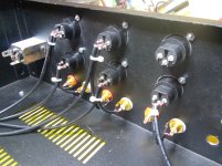
Ok, I started hooking up the wires and shield/negative is absolutely clear but as I hook it up now I have to bridge the XLR:s that are not in use and then I started thinking of a nice way to do the bridging cause I don't want to have the bridge in the open (I know it is on the back side of the pre, it is not visible but I am that way, either it is perfect or it is not😱😱). I came to the conclusion that I can buy some XLR male contacts, bridge them inside and put in the unused contacts but..... NO, if it is not perfect then do it correct instead.😡
It would though be very neat to have a small switch on the back beside the incoming channel where I can toggle RCA vs XLR. The place I have but since my brain is out of order I am just..... bla bla bla.... HOW!
Should I use a DPDT switch or..... DPST..... I bloody don't know (at least not today or tomorrow cause I have another night shift today) and then the question is, how do I hook it up in a smart way.
I have place to put a small connection block just underneath the XLR/RCA and I was thinking a miniature toggle switch beside the XLR, one for each channel so I can switch easy from balanced to unbalanced for each channel.
Yes It should be done digitally but me... I am more of a analog type so I have to study like crazy to get the digital part but it will come but as I mentioned earlier in the thread, I want to listen now.... no, yesterday!
Anyone who want to contribute with a small scetch how to connect a toggle switch so that it go from balanced/unbalanced both right and left channel at the same time will be awarded a most lovely, wonderful and well tasing virtual beer or any other liquid they prefer, and if you are closeby then come and collect IRL!😀
I already know that I will rebuild it later (could be a year ahead or two, who knows) with control remote and all the digital stearing that was intended but for the moment I just want to get it playing, not do the studying.🙄
After a weekend working night shift my brain is not the slightest awake even if I am up and moving so I would appreciate some help.
Started wiring the inlets and think it is pretty neat so far but then I came to think about XLR vs RCA....??

Ok, I started hooking up the wires and shield/negative is absolutely clear but as I hook it up now I have to bridge the XLR:s that are not in use and then I started thinking of a nice way to do the bridging cause I don't want to have the bridge in the open (I know it is on the back side of the pre, it is not visible but I am that way, either it is perfect or it is not😱😱). I came to the conclusion that I can buy some XLR male contacts, bridge them inside and put in the unused contacts but..... NO, if it is not perfect then do it correct instead.😡
It would though be very neat to have a small switch on the back beside the incoming channel where I can toggle RCA vs XLR. The place I have but since my brain is out of order I am just..... bla bla bla.... HOW!
Should I use a DPDT switch or..... DPST..... I bloody don't know (at least not today or tomorrow cause I have another night shift today) and then the question is, how do I hook it up in a smart way.
I have place to put a small connection block just underneath the XLR/RCA and I was thinking a miniature toggle switch beside the XLR, one for each channel so I can switch easy from balanced to unbalanced for each channel.
Yes It should be done digitally but me... I am more of a analog type so I have to study like crazy to get the digital part but it will come but as I mentioned earlier in the thread, I want to listen now.... no, yesterday!
Anyone who want to contribute with a small scetch how to connect a toggle switch so that it go from balanced/unbalanced both right and left channel at the same time will be awarded a most lovely, wonderful and well tasing virtual beer or any other liquid they prefer, and if you are closeby then come and collect IRL!😀
I already know that I will rebuild it later (could be a year ahead or two, who knows) with control remote and all the digital stearing that was intended but for the moment I just want to get it playing, not do the studying.🙄
Pass DIY Addict
Joined 2000
Paid Member
Here is a wiring diagram that someone made for me years ago when I had the same question.
I used a simple SPST switch to make the connection.
An externally hosted image should be here but it was not working when we last tested it.
I used a simple SPST switch to make the connection.
As I said, my brain refuse to do thinking. Plus would always go through to pcb but you toggle the shield and minus?
Then you can use one pole but for both right and left you would need a two pole switch?
Then you can use one pole but for both right and left you would need a two pole switch?
Pass DIY Addict
Joined 2000
Paid Member
You are correct: use a dual pole switch for a stereo amp. I used a monopole switch because I built mono amps.
Update and...... Yes! Question as usual.
Time.... yes, that is the thing, time is missing or I have a wife who is absolutely phenomenal at delegating things to do when I have spare time.😛
I am currently building on the Aleph P1.7 and I have connected everything on the backside now or at least signal cables. I can switch each channel between balanced or unbalanced both in an out. I am switching both minus and plus, it is just the shield that bypass all the switches.😎
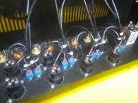
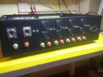
Then I realized that the distance between pre amp boards and incoming AC was too tight so I have made new sets of holes to be able to mount the pre amp boards closer to the front leaving some distance to incoming AC.
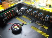
Now I am coming to the point where I am going to prepare for the mains and I have a question as usual (better to confirm my thoughts than have to do the whole amplifier several times).
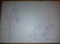
I want to put fuses both on primary side and secondary side along with a relay so I don't have to pull 230 VAC through the whole chassis. The calculation of the fuse on the primary side I have done using 50VA/230VAC since I have two transformers of 50VA, one for each channel, and then I get appr. 217 mA which I round up to closest fuse and that would be 250 mA/250V.
Does it matter that I have two transformers, my logic says that it shoud not matter but I might be wrong so maybe it is better to put one fuse on each transformers primary side (after relay and connection block) but then again, do I need the first fuse then (for picture look further down)??
But the secondary side????
I don't know how to calculate the fuse on the secondary side. It should not have anything to do with the transformer on secondary side but only with what current is used by the boards so.....
I have heard that the Aleph P1.7 should draw approximately 50-60 mA at normal use but my memory is not to trust in this matter, it could be another figure here but the question is; how do I use/calculate a value for the fuse?
I would also like that someone could just confirm my planned connection but I think that my thinking is right. All connections should start with a fuse so to say. On the primary side the fuse should be before the relay and on the secondary side it should be before the rectifiers, or.....?
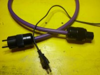
I also recieved a fun parcel from China in the beginning of the month so I have made some new power cables in the evenings (closer to some hours into the new day). I could never imagine that it should be so much difference but it is significant how much the power cable is affecting the sound. Right now I am testing my tube amp (Damn Good 300B) and changing the cable was a big WOW! Instruments are, not necessarely further apart in the 3D sound image, but defenitely more separated, there is air between the instruments. Then silent passages that was really blacked out with the tube amp got more.... pitch dark. No, but it got calmly black if you can understand the description, not just black but with a sence of tranquility also..... Well new cables are here to stay and more is ordered.
And, NO, it is not my earlier power cable for the amp on the picture, it is just there for comparation.
Time.... yes, that is the thing, time is missing or I have a wife who is absolutely phenomenal at delegating things to do when I have spare time.😛
I am currently building on the Aleph P1.7 and I have connected everything on the backside now or at least signal cables. I can switch each channel between balanced or unbalanced both in an out. I am switching both minus and plus, it is just the shield that bypass all the switches.😎


Then I realized that the distance between pre amp boards and incoming AC was too tight so I have made new sets of holes to be able to mount the pre amp boards closer to the front leaving some distance to incoming AC.


Now I am coming to the point where I am going to prepare for the mains and I have a question as usual (better to confirm my thoughts than have to do the whole amplifier several times).
I want to put fuses both on primary side and secondary side along with a relay so I don't have to pull 230 VAC through the whole chassis. The calculation of the fuse on the primary side I have done using 50VA/230VAC since I have two transformers of 50VA, one for each channel, and then I get appr. 217 mA which I round up to closest fuse and that would be 250 mA/250V.
Does it matter that I have two transformers, my logic says that it shoud not matter but I might be wrong so maybe it is better to put one fuse on each transformers primary side (after relay and connection block) but then again, do I need the first fuse then (for picture look further down)??
But the secondary side????
I don't know how to calculate the fuse on the secondary side. It should not have anything to do with the transformer on secondary side but only with what current is used by the boards so.....
I have heard that the Aleph P1.7 should draw approximately 50-60 mA at normal use but my memory is not to trust in this matter, it could be another figure here but the question is; how do I use/calculate a value for the fuse?
I would also like that someone could just confirm my planned connection but I think that my thinking is right. All connections should start with a fuse so to say. On the primary side the fuse should be before the relay and on the secondary side it should be before the rectifiers, or.....?

I also recieved a fun parcel from China in the beginning of the month so I have made some new power cables in the evenings (closer to some hours into the new day). I could never imagine that it should be so much difference but it is significant how much the power cable is affecting the sound. Right now I am testing my tube amp (Damn Good 300B) and changing the cable was a big WOW! Instruments are, not necessarely further apart in the 3D sound image, but defenitely more separated, there is air between the instruments. Then silent passages that was really blacked out with the tube amp got more.... pitch dark. No, but it got calmly black if you can understand the description, not just black but with a sence of tranquility also..... Well new cables are here to stay and more is ordered.
And, NO, it is not my earlier power cable for the amp on the picture, it is just there for comparation.

1.seeing all those coaxial cables , I'm almost feeling abundance of capacitance in signal route ..... 
2.same as you calc fuse for primary (VA/Vac) , calc fuse for secondary ; say that you have 2x24Vac secs (48Vac with CT) , then fuse is going to be 50Va/48Vac =1A ; depending of cap bank afterwards , choose F or T fuse , or increase it one notch
3.if you have two xformers , real engineer approach is to fuse them separately ;besides that , sketch is OK
1.seeing all those coaxial cables , I'm almost feeling abundance of capacitance in signal route .....
2.same as you calc fuse for primary (VA/Vac) , calc fuse for secondary ; say that you have 2x24Vac secs (48Vac with CT) , then fuse is going to be 50Va/48Vac =1A ; depending of cap bank afterwards , choose F or T fuse , or increase it one notch
Thanks for quick answer Zen Mod. I know it is a lot of cables but I am going to keep them as short as possible (appr. 10-12 cm maximum).
When it come to point 2, now I understand so now I have 2x30 and that would give 0.83A so I could use 1A fuse then.
When you say F or T fuse depending on the cap bank, how do you mean? I know that F (fast) and T (slow) but how does it depend on the cap bank?
Then, if I want to add a thermistor, where do I put it in my scetch? Should it be placed before the relay or could I also here put it right after the secondary before the rectifiers?
well, T vs. F - you'll remember it best if you figure it out by your self from datasheets 
thermistor - for that amount of Jules , you don't need (NTC in role of) soft start.
however , when speakig of NTC , topreserve full dual mono setup , you need separate ones (one per channel) going from audio GND to chassis

thermistor - for that amount of Jules , you don't need (NTC in role of) soft start.
however , when speakig of NTC , topreserve full dual mono setup , you need separate ones (one per channel) going from audio GND to chassis
- Status
- Not open for further replies.
- Home
- Amplifiers
- Pass Labs
- My first Aleph....Pass Labs.... experience!