Capacitance, some yes!
Just out of curiousity I did measure and I have ~0.9 nF on the now existing length and I presume I will shorten about 1/4-1/3 of that length when I connect to the relay controlled switch board that I wait for. Would it be a problem that I have to consider?
I know that if I did it with a digital controller board I could go for shorter signal cables but as for the moment I do it mechanically and it require some extra cable.
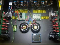
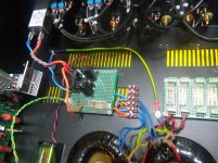
1.seeing all those coaxial cables , I'm almost feeling abundance of capacitance in signal route .....
Just out of curiousity I did measure and I have ~0.9 nF on the now existing length and I presume I will shorten about 1/4-1/3 of that length when I connect to the relay controlled switch board that I wait for. Would it be a problem that I have to consider?
I know that if I did it with a digital controller board I could go for shorter signal cables but as for the moment I do it mechanically and it require some extra cable.
well , I'm always content arranging things to have short cable routes , and using twisted solid core pairs - tiny 0.15mm , silvered copper with PTFE(-ish) isolation
ground question
Have a discussion with myself about ground!
I have pulled ground from the inlet ( IEC) and attached as close as possible but I have ground also from the transformers that should connect close to the transformers. Can I connect a wire from transformer ground to inlet ground?
Have a discussion with myself about ground!
I have pulled ground from the inlet ( IEC) and attached as close as possible but I have ground also from the transformers that should connect close to the transformers. Can I connect a wire from transformer ground to inlet ground?
static shields ?
Could be but I am not home to check. If it is then they don't connect to ground or?
you can have only two "grounds" on xformer - one is audio GND , second static shield
first forming main audio GND/going to cap bank , second going to same screw where you connected safety GND to chassis
first forming main audio GND/going to cap bank , second going to same screw where you connected safety GND to chassis
Ok, late evening!!
Home again😀
Working in the night is not that funny no more but... someone have to do it.
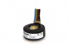
Checked the transformer now when I came home.... 03:30 and it look like this

To me that looks defenitely like ground, "0" is yellow/green so I want to connect it to the chassie close to the transformers and then lead a wire to saftey ground so I dont have ground loops running around my chassis.
When we are at it I have two 50VA transformers with 2x30V secondary. They look exactly the same as on the picture above so...
Primary side Blue/Blue and Yellow/Green which is the ground
Secondary side 2x Red and 2x Black.
I have understood that I take, from left to right (or right to left for the ones who want to do things differently but then you have to imagine the colours differently....😛😛) Red (first pair) goes to Aleph P1.7 AC, Second Red (first pair) goes to Black (second pair) and second Black (second pair) goes to Aleph P1.7 AC. This way I would take out 1x60V instead of 2x30V, have I got it right?
If you think that I am crazy asking this is because it is now 04:10 and I have just been working 9 hours so bare with me, pls!😉
Home again😀
Working in the night is not that funny no more but... someone have to do it.
Checked the transformer now when I came home.... 03:30 and it look like this

To me that looks defenitely like ground, "0" is yellow/green so I want to connect it to the chassie close to the transformers and then lead a wire to saftey ground so I dont have ground loops running around my chassis.
When we are at it I have two 50VA transformers with 2x30V secondary. They look exactly the same as on the picture above so...
Primary side Blue/Blue and Yellow/Green which is the ground
Secondary side 2x Red and 2x Black.
I have understood that I take, from left to right (or right to left for the ones who want to do things differently but then you have to imagine the colours differently....😛😛) Red (first pair) goes to Aleph P1.7 AC, Second Red (first pair) goes to Black (second pair) and second Black (second pair) goes to Aleph P1.7 AC. This way I would take out 1x60V instead of 2x30V, have I got it right?
If you think that I am crazy asking this is because it is now 04:10 and I have just been working 9 hours so bare with me, pls!😉
I had to find a solution for my transformers and cable routing.

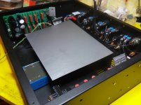
I had an idea to separate all mains from low voltage and suddenly I realized that it was not that simple but after some thinking I came up with this solution.


I use a steel plate that come up over the transformers and regulators needed. This way I keep the high and low voltage "downstairs" while signals will only be "upstairs" with minimum of interference between the two.🙄
My idea also fit the Aleph P1.7 pcb:s that Koja (really nice layout having signals in one end and feeding in the other end) have made since I have 60V feeding towards the front of the pre amp while signals go in/out towards the back of the chassis. If needed I can seal the "bottom floor" entirely by mounting sides on the steel platform but I think this solution will be pretty sufficient.
I noticed something that I have to ask about though.😕
I have made a simple L7805 regulator for the relay switching on/off the mains that is feeded from a 9V battery but today when I wanted to test the transformers it turn out that the battery is half dead and didn't activate the realy that is a 5V relay. So my qustion is does the relay draw any current when not activated?? (And yes, I am going to put another fuse so I have separate fuses on each transformer)😎
I was of the impression that if I don't press the on button there should not be any current flowing so why is it that my battery is discharged....??🙁

Can it be that the caps in the regulator is discharging after a while when unused and that the battery compensate that discharge all the time so that some small current is drawn all the time??
Then the question is, can I prevent this from happening or can I run the relay directly without the regulator or do I have to switch to another realy then (or battery)?
I thought that the battery should work for longer than 2 days even if it was not that fresh from start otherwhise I have to take 230V front of the chassis and put an ordinary switch up front but my idea was to work a relay via battery not to have 230V running through the whole chassis.🙁

I had an idea to separate all mains from low voltage and suddenly I realized that it was not that simple but after some thinking I came up with this solution.


I use a steel plate that come up over the transformers and regulators needed. This way I keep the high and low voltage "downstairs" while signals will only be "upstairs" with minimum of interference between the two.🙄
My idea also fit the Aleph P1.7 pcb:s that Koja (really nice layout having signals in one end and feeding in the other end) have made since I have 60V feeding towards the front of the pre amp while signals go in/out towards the back of the chassis. If needed I can seal the "bottom floor" entirely by mounting sides on the steel platform but I think this solution will be pretty sufficient.
I noticed something that I have to ask about though.😕
I have made a simple L7805 regulator for the relay switching on/off the mains that is feeded from a 9V battery but today when I wanted to test the transformers it turn out that the battery is half dead and didn't activate the realy that is a 5V relay. So my qustion is does the relay draw any current when not activated?? (And yes, I am going to put another fuse so I have separate fuses on each transformer)😎
I was of the impression that if I don't press the on button there should not be any current flowing so why is it that my battery is discharged....??🙁

Can it be that the caps in the regulator is discharging after a while when unused and that the battery compensate that discharge all the time so that some small current is drawn all the time??
Then the question is, can I prevent this from happening or can I run the relay directly without the regulator or do I have to switch to another realy then (or battery)?
I thought that the battery should work for longer than 2 days even if it was not that fresh from start otherwhise I have to take 230V front of the chassis and put an ordinary switch up front but my idea was to work a relay via battery not to have 230V running through the whole chassis.🙁
Relay Switch?
Ok, I have realized that I am using a non latching relay.... which is not optimal since it is all the time drawing current from the battery as long as it is open.... which in turn is draining the battery as long as I have the P1.7 running.
I got myself a new latching relay, Omron G5RL-U1-E, and for some reason it don't want to work at all. Connected it to 5V with at and it did switch twice when I tested it but then it have given up so it don't switch between the two poles. I can hear that it want to switch but the connector is not moving from were it is to the other pole, have I burnt it or is it just a mechanical hick up? I did test it up side down and that was maybe not good since the mecanism can have got hung up by this.
Anyway, I will get a new one but my question is how to implement the relay in a smart way cause I do want an ordinary ON/OFF button (for some unexplainable reason I don't like the momentanious push buttons that is requiered for the latching relay) so how can I do this?
Anyone who can give me a hint? I have been looking around and I only find implementations with minimum two relays and still it need the wimpy push button that I don't like.
Do I find ready made modules for this?
Ok, I have realized that I am using a non latching relay.... which is not optimal since it is all the time drawing current from the battery as long as it is open.... which in turn is draining the battery as long as I have the P1.7 running.

I got myself a new latching relay, Omron G5RL-U1-E, and for some reason it don't want to work at all. Connected it to 5V with at and it did switch twice when I tested it but then it have given up so it don't switch between the two poles. I can hear that it want to switch but the connector is not moving from were it is to the other pole, have I burnt it or is it just a mechanical hick up? I did test it up side down and that was maybe not good since the mecanism can have got hung up by this.

Anyway, I will get a new one but my question is how to implement the relay in a smart way cause I do want an ordinary ON/OFF button (for some unexplainable reason I don't like the momentanious push buttons that is requiered for the latching relay) so how can I do this?
Anyone who can give me a hint? I have been looking around and I only find implementations with minimum two relays and still it need the wimpy push button that I don't like.
Do I find ready made modules for this?
Hello guys, I guess this is the right thread to ask. I've got question about Aleph 3 transistors match. I mean the input pair should be matched at 10mA current and the output pais at 1A current? Am I right?
Hello guys, I guess this is the right thread to ask. I've got question about Aleph 3 transistors match. I mean the input pair should be matched at 10mA current and the output pais at 1A current? Am I right?
That sounds about right.
Thank you. I am reading about this Aleph J now. Do you think it's better choice than that old good Aleph 3? 25-35Watts is perfectly fine for me. Or maybe is there something else that is improved more than the Aleph J? I'm most interested in natural sounding, whatever it takes.
if you want knock-out of FW schematic , buy one from the Store
if you want something more versatile ,but still Aleph J , look for Babelfish J
read first , think about , then choose
if you want something more versatile ,but still Aleph J , look for Babelfish J
read first , think about , then choose
Fuses?
I do and do again and I re-do, so it is when you build your plan on the road.🙄
Ok, I had two fuses on incoming AC, one for each transformer since I build my preamp as dual mono. Now I realized that when I connect my third transformer that is going to run relays on both amp boards, signal switch and volume control then I will need another fuse for that transformer but now to my problem (don't like to use this word, it is more of an obstacle), I have a transformer that leave 12 VA from 230 V to the secondary side that give 2 x 15 V.
The secondary side is no problem but calculating this for the primary side would leave 12/230 but that is only 0,052 mA and my problem is finding fuses that small.🙁
Since I don't have any capacitor bank that has to charge for the purpose can I use a 100 mA fast fuse instead of a slow one?
I presume that slow fuses are better used when you have a capacitor bank that have to charge but in this case I have one cap 220 uF on the Volume board otherwise there is no caps at all and the transformer is not of the size that would require a slow fuse.
- Status
- Not open for further replies.
- Home
- Amplifiers
- Pass Labs
- My first Aleph....Pass Labs.... experience!
