what will be the differens since I have used the Dubier 2 uF??
When the amplifier is struck by lightning, you will be able to salvage the cap.
😎
Now I got embarrassed.....
50 + and red on my cheeks.....
Usually it is only my wife who manage that but I am honored.... Papa was here commenting on my work, WOW!😎😎
I find this really fantastic that the inventor of this pre amp and power amp is here to both comment and give us the hints that we sometimes need to fulfill our dreams.
I must say that when it come to reproducing music I have through my years understood some fundamental things about what makes music worth listening to even if I don't have the electronical understanding and education but if I put it like this, I think that most people here understand what I mean;
Reading about some of our heroes out there/here (Papa is here) I can only conclude that I find these above mentioned statements in all (almost at least, everybody can be wrong sometime) the products from example Jean Hiraga, Kaneda, Allen Wright and of cause Nelson Pass and these are my heroes within equipment for reproducing music because they have understood and developed these fundamental knowledges to perfection. Yes there are more heroes out there but I don't know them all but I keep to my favourites.
I am really glad that I started these projects and to be honest, I did not know that much about Nelson Pass before starting but what caught my interest was that I read somewhere that he was making amps based on the same way of thinking that I had heard about Jean Hiraga already in the seventies and that made my decision, no unnessecary components of doubtful quality, the right things in the right place and with power enough to heat the house (if needed).
It can't be wrong so go for it!!
Thank you Nelson for your efforts and that you also share them with us, unknowing but interested, souls who only want to enjoy music the way it is supposed to sound.
(If it sounds like as-king then it might be but I am old enough to stand for it!)😀
50 + and red on my cheeks.....
Usually it is only my wife who manage that but I am honored.... Papa was here commenting on my work, WOW!😎😎
I find this really fantastic that the inventor of this pre amp and power amp is here to both comment and give us the hints that we sometimes need to fulfill our dreams.
I must say that when it come to reproducing music I have through my years understood some fundamental things about what makes music worth listening to even if I don't have the electronical understanding and education but if I put it like this, I think that most people here understand what I mean;
Simple - that is something I have also seen and understood working as a civil engineer within natural resources and construction - with all our knowledge and education we tend to make things very much more complicated than is needed
Power - many times we make a calculation and know that if we use numerical analysis as our tool then we can choose the 95% percentile, the 98% percentile or whatever our choice will be, but again experience tell me that when we think that we are safe then we meet a situation where we need more power than we could ever dream of so we don't have what is needed just at that specific moment and we get dissapointed.
Logic - things are not more complicated than they ought to be. If we have a situation where things have to be loose, fluctuating or to travel.... then let things loose, let it swing or fluctuate like crazy or you will have serious problem coming to you. If they are intended to be firm, stable and consistant, then see so that things don't move, they should be firm and not fluctuate at any cost. Have you seen a mobile crane not beeing able to lift freely because of some wires restricting the movement of the crane..... 60 tons going down in 3 seconds make the earth shake, I promise you, this don't only apply on electronical equipment but everywhere.
Accuracy - if something demand a certain level of precision, don't leave things to be choosen from the air. There is an intention by choosing that special component or that precise value or that special treatment and many times it fall back on the above mentioned logic. Don't start messing with cm/inch when the work is demanding micrometers/ppm to be done right, you will end up with a mess and then someone will tell you; "do it again, do it right"!!
Reading about some of our heroes out there/here (Papa is here) I can only conclude that I find these above mentioned statements in all (almost at least, everybody can be wrong sometime) the products from example Jean Hiraga, Kaneda, Allen Wright and of cause Nelson Pass and these are my heroes within equipment for reproducing music because they have understood and developed these fundamental knowledges to perfection. Yes there are more heroes out there but I don't know them all but I keep to my favourites.
I am really glad that I started these projects and to be honest, I did not know that much about Nelson Pass before starting but what caught my interest was that I read somewhere that he was making amps based on the same way of thinking that I had heard about Jean Hiraga already in the seventies and that made my decision, no unnessecary components of doubtful quality, the right things in the right place and with power enough to heat the house (if needed).
It can't be wrong so go for it!!
Thank you Nelson for your efforts and that you also share them with us, unknowing but interested, souls who only want to enjoy music the way it is supposed to sound.
(If it sounds like as-king then it might be but I am old enough to stand for it!)😀
When the amplifier is struck by lightning, you will be able to salvage the cap.
😎
hahaha, I see: 1000V DC 😀
ztx vs bc
A question when I am at it....
Here in Sweden it is a little tricky to get hold of ZTX so I decided to go for the BC639/640 since they where as close as I could get to match the ZTX450/550.
I have measured at room temperature and at 35 degrees celsius so I have a close match but also a some idea about temperature drift.
Now after matching I should start to solder but then I got confused, the Base, Collector and Emittor are somewhat strange or is it me being utterly stupid.
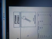
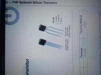
I am aware that it have been said that when using BC550/560 and other replacements you have to turn them 180 degrees but since I have choosen BC639/640 they seem to be different yet. Base is not any longer in the middle but as pin 3 so now it seem that I have to turn them like 90 degrees, cross the legs or....... am I right or utterly stupid???
Need others eyes on this one!
A question when I am at it....
Here in Sweden it is a little tricky to get hold of ZTX so I decided to go for the BC639/640 since they where as close as I could get to match the ZTX450/550.

I have measured at room temperature and at 35 degrees celsius so I have a close match but also a some idea about temperature drift.
Now after matching I should start to solder but then I got confused, the Base, Collector and Emittor are somewhat strange or is it me being utterly stupid.


I am aware that it have been said that when using BC550/560 and other replacements you have to turn them 180 degrees but since I have choosen BC639/640 they seem to be different yet. Base is not any longer in the middle but as pin 3 so now it seem that I have to turn them like 90 degrees, cross the legs or....... am I right or utterly stupid???
Need others eyes on this one!
go figure pinout by yourself
regarding matching - there is absolutely no need for that
ZM; I have figured it out, just that I had some 40 pieces of BC639/640 at home so since they match the ZTX in voltage and ampere I was only considering that at first. It was just when I started placing them on the board that I realized that pinout was different from other BC mentioned here at the forum. Will give me a little longer legs than intended and I have to crimp a protection on one of the legs where crossing the other. Not a problem just unconvenient.🙁
When it come to my effort in matching.....
Yes I know that is is not needed but on the other hand, now I have measured all my transistors for future need, I have also vague control over the thermal drift which mean that for other projects, it is done.
As for this project, building both the Aleph P1.7 and the Aleph J in parallell, I don't see the harm in matching all devices.
We are building a project were all resistors are to be matched down to at least 1 % (at the moment I am at 0.1 %), we are to use matched SJ74 so what is the harm in trying to match the transistors also?😉
I read in another thread here at the Pass Forum that matching all devices on the board would only result in a better end product.
We are back at my earlier post were I talked about power, accuracy and so on.
I might not be the brightest here in the electronical field but from earlier experiences I know that if I have two... identical, well producing machines, parts, PCB:s or any other construction that somehow affect or interact, via one or many parts (in this case the transformer in the Aleph J PSU and for the Aleph P 1.7 I have separated the PSU also), the less they will stress the total system and which will result in a more well behaving end product.
That is also one of the reason why we sometime tend to build monoblocks instead of squeezing in two channels in one box, isn't it?😉
Starts looking like christmas.....
Slowly, slowly things are put to place and I hope to have at least the P1.7 up this year (together with my Damn Good 300B amp that is also coming together). Yes I could have built it faster but I have a family also and since my working hours are a little odd I have to take care of the house also every now and then.😱
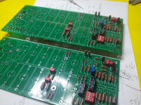
I did figure out the pinout so I had to change collector and base, after that they are the same as ZTX.
Now it looks like I have some transistors on the board that need to go to the toilet cause all of them have crossed legs.😀😀
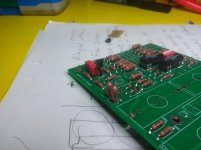
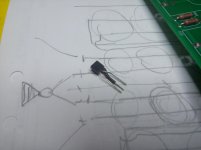
Slowly, slowly things are put to place and I hope to have at least the P1.7 up this year (together with my Damn Good 300B amp that is also coming together). Yes I could have built it faster but I have a family also and since my working hours are a little odd I have to take care of the house also every now and then.😱

I did figure out the pinout so I had to change collector and base, after that they are the same as ZTX.
Now it looks like I have some transistors on the board that need to go to the toilet cause all of them have crossed legs.😀😀


Heatsink??
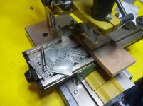
Don't know if you could call this a heatsink but it will, from theory 🙂confused:😕), dissipate some heat just like a heatsink.
Home made yes, but I have made them on basis of thermodynamic laws and the fact that eddie currents in the airflow, created by the many small holes will help the upward draft along the aluminium plate, tranferring the heat effectively to the surrounding air.😎
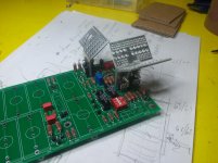
Now I only miss some very important caps and the relays missing in the picture then I am almost ready to heat it up the first time.
As far as I can measure resistance at this moment, measured at several points, indicate that the two channels are within 0.2 % of eachother and that I hope is a good sign.
By the way, do I need to put a heat sink for the brigde rectifier or is it ok with just a small one on the IRFP610 for the PSU??
Have not seen any on the bridge rectifier for other P1.7:s built here so I assume it runs cool enough.
Yes I need an attenuator as well but first thing first..... The founds this month had to be divided between many projects so unfortunately I am soon stuck for some weeks on this one but I am not sad cause I have a Aleph J that I have recieved some new things for also so building will be ongoing, just other objects.😀
Don't know if you could call this a heatsink but it will, from theory 🙂confused:😕), dissipate some heat just like a heatsink.
Home made yes, but I have made them on basis of thermodynamic laws and the fact that eddie currents in the airflow, created by the many small holes will help the upward draft along the aluminium plate, tranferring the heat effectively to the surrounding air.😎

Now I only miss some very important caps and the relays missing in the picture then I am almost ready to heat it up the first time.
As far as I can measure resistance at this moment, measured at several points, indicate that the two channels are within 0.2 % of eachother and that I hope is a good sign.
By the way, do I need to put a heat sink for the brigde rectifier or is it ok with just a small one on the IRFP610 for the PSU??
Have not seen any on the bridge rectifier for other P1.7:s built here so I assume it runs cool enough.
Yes I need an attenuator as well but first thing first..... The founds this month had to be divided between many projects so unfortunately I am soon stuck for some weeks on this one but I am not sad cause I have a Aleph J that I have recieved some new things for also so building will be ongoing, just other objects.😀
New to matching Mosfets
First time for many things this is, good training also for future projects.😀
I was measuring a number of irf610 for my Aleph P1.7 and yes I know that it is not needed for the irf610 on the power supply but now it is done and I am happy...... but...
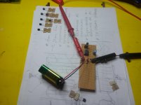
I made the set up on an evaluation board and used a 9V battery, a 2.2 kOhm resistor and then measuring the voltage from gate to.....drain..... right....no?
(I had a paper showing the set up so it is my memory that is failing now when writing, since it was the first time measuring Mosfets). Ok, I have the paper here (I did have to fetch it in the basement cause I did not save the picture but now it is in my computer also)🙄;
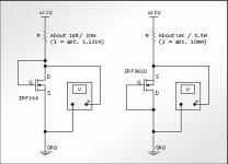
When I was ready measuring all 20 fets I started thinking that maybe I didn't have the right current running through the fet since I only took what was at hand so I tested with some other resistors and realized that things are happening inside those irf:s.
Going with 5 Ohm 5W made the fet running hotter and hotter and I had to save it at about 50 degrees Celsius couse I don't want to destroy things before they work properly but I also realized that with temperature the change in voltage was very significant and without cooling it can/will be like a run away train..... very fast!😱😱
At 2.2 kOhm 2W I had about 3.554-3.612 Volts from drain to source, very stable even after 5 minutes and easy to measure.😎
At 2 x 2.2 kOhm 2W in parallell, 1.1 kOhm and 4W then I had figures around 3.67-3.90 Volts, also stable after 5 minutes also very easy to measure😎
So, what should I really have done??
If I presume a voltage drop of 4 volts over the Mosfet (this is a figure I have seen on a webpage so I really don't know) then I have with 2.2 kOhm resistor about 2.2 mA (stable) passing the Mosfet.... or not?
With 1.1 kOhm it should then be about 4.5 mA (stable)and when running away it would have been about 1 A when starting.....
As you now realize I am not an expert in this but I think I learn new things everyday and that is most important and everyday is giving me more confidence for the nextcoming projects.😛
The reason for asking is that I am waiting for a number of ifrp240 for my Aleph J so now I want to do it correct so I don't have to try several times to get it right by trial and error (these have to be matched as close as possible so I want to do it correct the first time).
What current should I have running through the irf610:s to be shure (at least to be accurate about the measurements) about their function and should I eventually have more voltage from the beginning when measuring them??
Can I use the same values for irfp240 or can I find the actual values somewhere in the data sheets??
Can you please give me a hint I would appreceate it very much and I can continue learning.😉
First time for many things this is, good training also for future projects.😀
I was measuring a number of irf610 for my Aleph P1.7 and yes I know that it is not needed for the irf610 on the power supply but now it is done and I am happy...... but...
I made the set up on an evaluation board and used a 9V battery, a 2.2 kOhm resistor and then measuring the voltage from gate to.....drain..... right....no?
(I had a paper showing the set up so it is my memory that is failing now when writing, since it was the first time measuring Mosfets). Ok, I have the paper here (I did have to fetch it in the basement cause I did not save the picture but now it is in my computer also)🙄;

When I was ready measuring all 20 fets I started thinking that maybe I didn't have the right current running through the fet since I only took what was at hand so I tested with some other resistors and realized that things are happening inside those irf:s.
Going with 5 Ohm 5W made the fet running hotter and hotter and I had to save it at about 50 degrees Celsius couse I don't want to destroy things before they work properly but I also realized that with temperature the change in voltage was very significant and without cooling it can/will be like a run away train..... very fast!😱😱
At 2.2 kOhm 2W I had about 3.554-3.612 Volts from drain to source, very stable even after 5 minutes and easy to measure.😎
At 2 x 2.2 kOhm 2W in parallell, 1.1 kOhm and 4W then I had figures around 3.67-3.90 Volts, also stable after 5 minutes also very easy to measure😎
So, what should I really have done??
If I presume a voltage drop of 4 volts over the Mosfet (this is a figure I have seen on a webpage so I really don't know) then I have with 2.2 kOhm resistor about 2.2 mA (stable) passing the Mosfet.... or not?
With 1.1 kOhm it should then be about 4.5 mA (stable)and when running away it would have been about 1 A when starting.....
As you now realize I am not an expert in this but I think I learn new things everyday and that is most important and everyday is giving me more confidence for the nextcoming projects.😛
The reason for asking is that I am waiting for a number of ifrp240 for my Aleph J so now I want to do it correct so I don't have to try several times to get it right by trial and error (these have to be matched as close as possible so I want to do it correct the first time).
What current should I have running through the irf610:s to be shure (at least to be accurate about the measurements) about their function and should I eventually have more voltage from the beginning when measuring them??
Can I use the same values for irfp240 or can I find the actual values somewhere in the data sheets??
Can you please give me a hint I would appreceate it very much and I can continue learning.😉
I think the rule of thumb is to measure at the current you intend to use them.
For example, for IRFP240 in an Aleph J, each mosfet draw about 0.8 or 0.9A.
At these current values, you will want to attach the mosfet to a heatsink if
you want to run it long enough for the Vgs to stabilize and for the part to not
be damaged.
For example, for IRFP240 in an Aleph J, each mosfet draw about 0.8 or 0.9A.
At these current values, you will want to attach the mosfet to a heatsink if
you want to run it long enough for the Vgs to stabilize and for the part to not
be damaged.
As pointed out above, the best current to match at is the one you will
be using in your circuit.
That said, you can still get some pretty good measurements at different
current values, as the parts are pretty consistent when matched over a
range of currents - just try to keep in in the ballpark of the intended use.
be using in your circuit.
That said, you can still get some pretty good measurements at different
current values, as the parts are pretty consistent when matched over a
range of currents - just try to keep in in the ballpark of the intended use.
putting them on some sort of heatsink is helpful
you'll find here and there that some (members) are even using constant temperature shebangs instead of heatsink ..... which is necessary if you need precise results above greater number of devices in one span
you'll find here and there that some (members) are even using constant temperature shebangs instead of heatsink ..... which is necessary if you need precise results above greater number of devices in one span
Do again, do it right
Came up with the following,🙂

Found some 5 W resistors of total 8.6 Ohm and a suitable heatsink so now I at least came up to approximately 0.6 A when measuring without temperature drift.
Also came to think about that I have a temperature probe for my DMM so I could monitor the temperature at the same time.
Came to the conclusion that measuring at the same temperature was more important than waiting the same amount of time (in this case appr. 5 minutes to reach a near stable reading) for the readings.😉
Given a stable temperature of 27.2 degrees I now measured between 4.382 to 4.475 Volts for 10 of the mosfets then I had to give up cause the battery had lost about 0.2 Volts and I didn't have any new at home.
Yes I know, I am looking to buy a variable power supply but right for the moment I don't have it so battery will have to do for now.😛
Will continue tomorrow with the rest but I could at least pick out two that was measuring only 0.005 Volt difference for use in the power supply for my Aleph P1.7.
When I have measured all of them maybe I will choose another pair that are a little more off in measurment if I will be able to keep some better matched pairs by doing so, since the matching is not critical for the PSU.
Thank you all for advices and help.
Came up with the following,🙂

Found some 5 W resistors of total 8.6 Ohm and a suitable heatsink so now I at least came up to approximately 0.6 A when measuring without temperature drift.
Also came to think about that I have a temperature probe for my DMM so I could monitor the temperature at the same time.
Came to the conclusion that measuring at the same temperature was more important than waiting the same amount of time (in this case appr. 5 minutes to reach a near stable reading) for the readings.😉
Given a stable temperature of 27.2 degrees I now measured between 4.382 to 4.475 Volts for 10 of the mosfets then I had to give up cause the battery had lost about 0.2 Volts and I didn't have any new at home.
Yes I know, I am looking to buy a variable power supply but right for the moment I don't have it so battery will have to do for now.😛
Will continue tomorrow with the rest but I could at least pick out two that was measuring only 0.005 Volt difference for use in the power supply for my Aleph P1.7.
When I have measured all of them maybe I will choose another pair that are a little more off in measurment if I will be able to keep some better matched pairs by doing so, since the matching is not critical for the PSU.
Thank you all for advices and help.
Last edited:
If you are testing the IRF610 for the P1.7 then you can match at much lower current
values (say 40mA). That should help with the batter life.🙂
values (say 40mA). That should help with the batter life.🙂
If you are testing the IRF610 for the P1.7 then you can match at much lower current
values (say 40mA). That should help with the batter life.🙂
Sorry...battery...(too much baseball). 🙂
Yup!
I have realized that it is far toooo much baseball so everything on ice til I get myself a variable power supply. Most likely it will be bought at the same time as my irfp240 are arriving so I have a proper use for it emediately. 😀
Sorry...battery...(too much baseball). 🙂
I have realized that it is far toooo much baseball so everything on ice til I get myself a variable power supply. Most likely it will be bought at the same time as my irfp240 are arriving so I have a proper use for it emediately. 😀
- Status
- Not open for further replies.
- Home
- Amplifiers
- Pass Labs
- My first Aleph....Pass Labs.... experience!
