Ok, I have an old Hiraga Monster that I love....
I love the musicality in it even though I will have to rebuild the power supply cause it is far, far away from original but anyway, it plays music.
Then I have read here that Nelson Pass have made those lovely amps resembling about the simpleness and the ingenious solutions that I find in the Monster also so why not give it a try.
I bought some boards for the Aleph P1.7 from a fellow member and when collecting parts for that one I read about the Aleph J so why not go for that one at the same time and therefore I start this thread.
It will be my combined contribution to the Pass Labs forum.
Ok I have already been in to the Aleph J thread so here we go with my first idea.
http://www.diyaudio.com/forums/pass-labs/241729-aleph-j-illustrated-build-guide-182.html#post4792996
I was thinking of starting with the Aleph J PSU since I have most of the parts already at home. I will use the following PSU but to use all my unused caps I will do it with a twist.
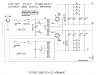
Since I want to do this amp the best way that I know I am going to try to separate AC from DC and shield as much as is possible to avoid unnecessary disturbance. I am also going to connect 5 x 15 000 uF plus 3 x 4700 uF in each rail, totally 178 200 uF for the PSU (and I get use of my caps laying here).
I will get an Dissipante 4U chassie for the build and I was thinking to get the balance right (don't like when an amp is back heavy or side heavy, it should be balanced) at the same time as I separate the AC and DC.
My idea is to take in the AC on the bottom in a shielded channel underneath the actual PSU that will be elevated about 25 - 30 mm. Transformer goes not all way front but fairly so and after that I place the caps. This whole elevation can be shielded in its entirety separating AC from DC. I think this will be optimal soundwise, the only but I can find is the yellow areas of the rails and here come a question to all of you who have already benefited from Nelson Pass generosity.
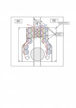
Edit: Sorry, see that the resistor on the right hand side ended up on the positive side instead of the negative side.... Hope you can forgive me for that.
Will I have problems with electromagnetic induction?? I know that it can affect the sound but I do belive that the induced field are not counterworking eachother the way the cables are layed out but still want to have some second opinion on this matter.
I love the musicality in it even though I will have to rebuild the power supply cause it is far, far away from original but anyway, it plays music.
Then I have read here that Nelson Pass have made those lovely amps resembling about the simpleness and the ingenious solutions that I find in the Monster also so why not give it a try.
I bought some boards for the Aleph P1.7 from a fellow member and when collecting parts for that one I read about the Aleph J so why not go for that one at the same time and therefore I start this thread.
It will be my combined contribution to the Pass Labs forum.
Ok I have already been in to the Aleph J thread so here we go with my first idea.
http://www.diyaudio.com/forums/pass-labs/241729-aleph-j-illustrated-build-guide-182.html#post4792996
I was thinking of starting with the Aleph J PSU since I have most of the parts already at home. I will use the following PSU but to use all my unused caps I will do it with a twist.

Since I want to do this amp the best way that I know I am going to try to separate AC from DC and shield as much as is possible to avoid unnecessary disturbance. I am also going to connect 5 x 15 000 uF plus 3 x 4700 uF in each rail, totally 178 200 uF for the PSU (and I get use of my caps laying here).
I will get an Dissipante 4U chassie for the build and I was thinking to get the balance right (don't like when an amp is back heavy or side heavy, it should be balanced) at the same time as I separate the AC and DC.
My idea is to take in the AC on the bottom in a shielded channel underneath the actual PSU that will be elevated about 25 - 30 mm. Transformer goes not all way front but fairly so and after that I place the caps. This whole elevation can be shielded in its entirety separating AC from DC. I think this will be optimal soundwise, the only but I can find is the yellow areas of the rails and here come a question to all of you who have already benefited from Nelson Pass generosity.

Edit: Sorry, see that the resistor on the right hand side ended up on the positive side instead of the negative side.... Hope you can forgive me for that.
Will I have problems with electromagnetic induction?? I know that it can affect the sound but I do belive that the induced field are not counterworking eachother the way the cables are layed out but still want to have some second opinion on this matter.
Last edited:
The radiation from AC wiring is small compared to the transformer.
Transformer location and shielding will dominate, as will ground wiring layout.
After you have addressed everything else as best you can, then get ready to
rotate the transformer for minimum noise on both channels.
😎
Now listening to "Woman in Blue" by Pepe Deluxe.
Available also on vinyl
Transformer location and shielding will dominate, as will ground wiring layout.
After you have addressed everything else as best you can, then get ready to
rotate the transformer for minimum noise on both channels.
😎
Now listening to "Woman in Blue" by Pepe Deluxe.
Available also on vinyl
I did grounding on my diy Aleph J this way,
like on the attached picture
.....and didnt need drawer Nr.5 😀 (referenced to YT link)
https://www.youtube.com/watch?v=pyxBCCco-K8&index=4&list=PLJ4m8UqchIDn1v3mk9XI97UHq_HBUSrXQ
No ground loops in side case 😉
Gnd point close to back plate.
Aleph J is best for grounding , there is only 4 resistor to be signal grounded.

Attachments
Last edited:
My other Aleph.....p1.7
Ok, the second one that I am doing right now.
I have started soldering on my Aleph P1.7 also. Almost done with the resistors but I also realized that my DMM did not manage the accuracy that is intended here so I had to give up the smaller resistors (below 100 ohm) for a couple of days but now I am back in business, I have got myself a old and used Fluke 8050A that manage 10 mOhms accuracy so now I can get the needed matching of components.
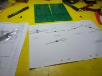
I have measured every singel resistor and matched them as thorough as possible so all resistors are within 0,1 % or better.

Fairly ok soldering I think, I don't do this for a living only as a hobby but I always try to do my very, very very best...... perfect (I hope/think).
As usual I have questions also. I want to build this pre amp as dual mono and I have started to think about the volume control that ought to be a relay controlled volume attenuator.
My question is will I lose something or gain something by using, for example, ladderbuilt attenuators for right and left control separately or should I still go for the relay controlled volume control?
I would like to adopt the thinking of late Allen Wright (the VacuumState amps for the unknowing). I found his discussion, in his book "Preamp CookBook", very interesting but also very obvious "the two channels should be held separated at all means"!
I don't think that anyone here disagree about this idea and at the same time everything is normally about compromise, at least HiFi equipment bought in a shop. But this is my build so I can do anything I want....if I want
That is why I consider separating the volume control also even if I might have to go from relays to ordinary attenuators. I already have two transformers, 60VA each so power is sufficient. Question is only, do I lose or gain..... or should I try.... both??
Last question for today, I am looking for a bridge rectifier that have been discussed here at the forum but unfortunately I can only find it at TEM.eu and those pr-cks have decided not to sell to private persons.
It is about the KBPC3510 by DC Components, I would like to have those for my Aleph J and eventually I can consider them for the Aleph P1.7 also....
Is there anyone out there who have found these bridge rectifiers somewhere else without having to pay $3-5 each for them. TME.eu charge about $1 each and that is more realistic.... if it were not for the fact that they don't what to sell them to me....!
Ok, the second one that I am doing right now.
I have started soldering on my Aleph P1.7 also. Almost done with the resistors but I also realized that my DMM did not manage the accuracy that is intended here so I had to give up the smaller resistors (below 100 ohm) for a couple of days but now I am back in business, I have got myself a old and used Fluke 8050A that manage 10 mOhms accuracy so now I can get the needed matching of components.

I have measured every singel resistor and matched them as thorough as possible so all resistors are within 0,1 % or better.

Fairly ok soldering I think, I don't do this for a living only as a hobby but I always try to do my very, very very best...... perfect (I hope/think).
As usual I have questions also. I want to build this pre amp as dual mono and I have started to think about the volume control that ought to be a relay controlled volume attenuator.
My question is will I lose something or gain something by using, for example, ladderbuilt attenuators for right and left control separately or should I still go for the relay controlled volume control?
I would like to adopt the thinking of late Allen Wright (the VacuumState amps for the unknowing). I found his discussion, in his book "Preamp CookBook", very interesting but also very obvious "the two channels should be held separated at all means"!
I don't think that anyone here disagree about this idea and at the same time everything is normally about compromise, at least HiFi equipment bought in a shop. But this is my build so I can do anything I want....if I want
That is why I consider separating the volume control also even if I might have to go from relays to ordinary attenuators. I already have two transformers, 60VA each so power is sufficient. Question is only, do I lose or gain..... or should I try.... both??
Last question for today, I am looking for a bridge rectifier that have been discussed here at the forum but unfortunately I can only find it at TEM.eu and those pr-cks have decided not to sell to private persons.
It is about the KBPC3510 by DC Components, I would like to have those for my Aleph J and eventually I can consider them for the Aleph P1.7 also....
Is there anyone out there who have found these bridge rectifiers somewhere else without having to pay $3-5 each for them. TME.eu charge about $1 each and that is more realistic.... if it were not for the fact that they don't what to sell them to me....!
regarding attenuators - whatever type of (resistive ones) you choose,switching is different issue - for ladder you can use either relays or (rotary) switch ; choice is yours
dual mono - either as separate cases or in one case - better separation and everything what goes with that
and - not least important - knowledge that you go overkill , and you'll have sweeter sleep with that 🙂
KBPC3510 is generic type of bridge - almost anything else is direct replacement
if you insist on overkill , buy anything from 10A and 250Vac upwards
To gain or not to gain...
Question was put in the Aleph P1.7 build thread but I move it here so I collect it in my own thread now.
Can I somehow make the gain switchable from the outside by not using the dip switch but instead have a selector on the front panel for different gain??
The reason for this is that I will be running this preamp towards two different types of power amps, one tube amp leaving around 10W and one Aleph J leaving about 25W. It would be nice to be able to change gain option from the front so I don't have to open it everytime I change.
Anyone here who can give me an idea about how to do it?
Would like to know.....
nice pcbs 🙂
the input attenuator is controlled by the dip switch settings. you can mount a 4-pole switch externally on the front. however these setting are a crude adjustment only to prevent a hot source from saturating AlephP input.
internal gain is set by the trim pot and the consensus was that the preamp was best sounding at high gain settings. (also in agreement with Pass saying: "a tired puppy is a happy puppy" 🙂). btw this can also be made adjustable externally and in discrete steps if you do not like the trimmer; I almost did what Ralph did here but decided against it since the pcb was already pretty big:
VV3 / Aleph P Ver. 1.7 Clone – RStAudio.de
for gain matching between amps when multi-amping the best is to use different volume control settings for each and have a master volume control that moves them together up & down; (for example I set two Dantimax VolCont2 boards separately by the knob and then move them both together by the same remote). his Control2 board though should be able to achieve this by programmed settings.
Last edited:
Schematics
Zen Mod, sorry for a late reply but you know, had to drive a bus today also and just came home.
Ok this is the situation;Schematics..... The PCB;s are made by Koja here at the forum and from what I do understand the boards are based directly on the original shematics presented in the Aleph P1.7 Service Manual so I do belive that you have been around both the schematics and most likely you have already seen Kojas PCB.
added clarification re: the 4-pole dipswitch:
switches 1 & 2 control input attenuator settings and switches 3 & 4 ground input and output respectively if either is to run unbalanced. Sorry, it has been a while since I did that board so the memory is a bit shady. dipswitch only controls REED relay connections for the best contact quality (probably an overkill but that's what diyaudio is all about, right? sleeping better 😴.
yes the schematic is the original Pass for v1.7.
anyways, your question was about gain matching and I already answered that.
Aleph J
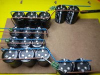
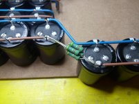
Now I have at least finished the caps for the power supply and I am rather satisfied with the result. Now I just have to locate a transformer and unfortunately it has to wait..... til next month I think....
By the way, I have used a 0.1 uF Mylar cap as filtercap but I would like a second hand opinion on Mylar caps for this use, please! Eventually also on the value but it is usually working rather good and everything can be changed if needed.
But I don't have to be without work since these small beauties turned up together with some matching fets....😛😛
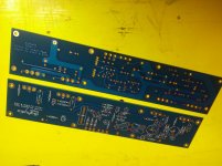
I am also waiting for some Vishay Dale resistors that are on the way so I can finish the Aleph P1.7 with resistors and I can also start stuffing the Aleph J PCB:s. That is a good thing with many projects at the same time cause you always have something to do.....
Now I have at least finished the caps for the power supply and I am rather satisfied with the result. Now I just have to locate a transformer and unfortunately it has to wait..... til next month I think....
By the way, I have used a 0.1 uF Mylar cap as filtercap but I would like a second hand opinion on Mylar caps for this use, please! Eventually also on the value but it is usually working rather good and everything can be changed if needed.


But I don't have to be without work since these small beauties turned up together with some matching fets....😛😛

I am also waiting for some Vishay Dale resistors that are on the way so I can finish the Aleph P1.7 with resistors and I can also start stuffing the Aleph J PCB:s. That is a good thing with many projects at the same time cause you always have something to do.....
I am not sure you have the top last two caps hooked correctly. They appear to be wrong. You also need to connect the center to create a ground. Turn the last two two top caps the same as the ones before it and then tie the brown and blue center wires together to form a common or ground. You need a V+ and V- and ground. As far as a mylar it should work as well as poly in that job as a snubber.
Last edited:
I am not sure you have the top last two caps hooked correctly. They appear to be wrong. You also need to connect the center to create a ground. Turn the last two two top caps the same as the ones before it and then tie the brown and blue center wires together to form a common or ground. You need a V+ and V- and ground. As far as a mylar it should work as well as poly in that job as a snubber.
Wdecho;
You are absolutely right about the two-grouped caps (up in the pic). Really big miss from my part, thanks for your eyes.
About center leaders, yes they go together but I am waiting for spade connectors to make it neat since they will be part of star ground when finished.
Every seasoned builder, tinkerer, designer has had the big bang early in the morning. It is a good wake up call. If you really want to go an extra mile install 2 motor run caps for the last caps in the chain.
...If you really want to go an extra mile install 2 motor run caps for the last caps in the chain.
How does that affect the sound?
I have not actually ever A/B'ed the difference in sound even if I could do it quick enough to tell the difference. A motor run cap is a high quality film cap and in principle a film cap is preferred over an electrolytic. If my memory is correct it is quicker than an electrolytic cap. Maybe the more technical guys will speak up here.
Many designers install snubber film caps across an electrolytic in their PS. Nelson shows a 10uf film cap for the last cap in the first Burning amp PS section as well. I use a 40uh motor run cap whenever possible in tube builds and now SS builds.
http://www.firstwatt.com/pdf/art_ba1.pdf
Page #2
Many designers install snubber film caps across an electrolytic in their PS. Nelson shows a 10uf film cap for the last cap in the first Burning amp PS section as well. I use a 40uh motor run cap whenever possible in tube builds and now SS builds.
http://www.firstwatt.com/pdf/art_ba1.pdf
Page #2
Some update and new questions
Have done some more soldering on my both Alephs (in fact it feel nice to have two in the pipeline but with limited budget I have to make choices all time.....p1.7 or J....p1.7 or J... but I always have somthing to do).
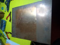
By the way, found a small copper plate at second hand that will be for my future restoration of my Hiraga Monster but I will use some for star ground in the Aleph J also. 450 x 350 mm and 2 mm thick.... nice, and I only paid like $5.50 so I couldn't resist.
The J looks like this today cause I was going through some boxes and since I have noticed earlier that some people here have used 2 uF instead of 1 uF I took out some Cornell Dubier that I had laying around to no use.
The 220 uF was some Nichikon Muse that I also had laying around at home, 50 V though but still usable.
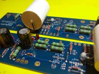
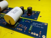
Now my question, what will be the differens since I have used the Dubier 2 uF??
What can I expect soundwise and how much will it affect?
It is no problem to change those afterwords but will I affect the end result so that I will be dissapointed or is it marginal?
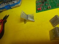
Now to my "Ihavetomuchtimetowaste"-work on my P1.7. I was thinking of fixing some heatsinks for the IRF:s. Question will this be too little or is it worth a try??
Aluminium is 2 mm thick and 26 mm wide and total length around 50 mm I will use them back to back so center between the IRF:s will be 4 mm aluminium with thermal grease between.
Am I working unnessecarely much or will it be enough?
Have done some more soldering on my both Alephs (in fact it feel nice to have two in the pipeline but with limited budget I have to make choices all time.....p1.7 or J....p1.7 or J... but I always have somthing to do).
By the way, found a small copper plate at second hand that will be for my future restoration of my Hiraga Monster but I will use some for star ground in the Aleph J also. 450 x 350 mm and 2 mm thick.... nice, and I only paid like $5.50 so I couldn't resist.


The J looks like this today cause I was going through some boxes and since I have noticed earlier that some people here have used 2 uF instead of 1 uF I took out some Cornell Dubier that I had laying around to no use.
The 220 uF was some Nichikon Muse that I also had laying around at home, 50 V though but still usable.


Now my question, what will be the differens since I have used the Dubier 2 uF??
What can I expect soundwise and how much will it affect?
It is no problem to change those afterwords but will I affect the end result so that I will be dissapointed or is it marginal?
Now to my "Ihavetomuchtimetowaste"-work on my P1.7. I was thinking of fixing some heatsinks for the IRF:s. Question will this be too little or is it worth a try??
Aluminium is 2 mm thick and 26 mm wide and total length around 50 mm I will use them back to back so center between the IRF:s will be 4 mm aluminium with thermal grease between.
Am I working unnessecarely much or will it be enough?

- Status
- Not open for further replies.
- Home
- Amplifiers
- Pass Labs
- My first Aleph....Pass Labs.... experience!


