I cut those out in the garage and kerfed the copper out for my voids on both sides.
I didn't catch that the first time I read it -- cool! Great idea. 🙂
Keep at it, you are making good progress!
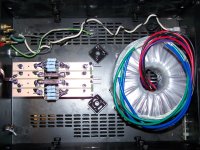
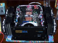
Do you think the rectifiers & cap bank are too close to the toroid?
It's elbows to buttholes in there!
Just don't forget to properly shield the elbows, and tie the buttholes to a good star ground.....(!) 😀
OK, OK, enough of my jocularity here.... 🙂 You have plenty of room on your chassis. Lots of real estate in your design, when you compare it to my F5 layout:
http://www.diyaudio.com/forums/pass...usic-different-drummer.html?highlight=drummer
UGH!!!!!
I forgot how much drill & tap sucks.
I broke my 6-32 tap on the first hole.
So far I have only 2 holes left and it has been smooth sailing.
I forgot how much drill & tap sucks.
I broke my 6-32 tap on the first hole.
So far I have only 2 holes left and it has been smooth sailing.
OK......I'm going to run my fans in series for a 24V load.
I have four fans, two for each side.
Can I pull my +24V per pair before the P/S resistors and not muck stuff up?
I would like to run 1 pair per rail.
I don't want to pop anything because shipping on any 1 item will cost more than the item.
I have four fans, two for each side.
Can I pull my +24V per pair before the P/S resistors and not muck stuff up?
I would like to run 1 pair per rail.
I don't want to pop anything because shipping on any 1 item will cost more than the item.
Don't worry about the fans yet, you have enough heatsink to keep things from burning up. (at normal bias)
Get the amp working and then finish the fans. But yes, you can take the fan power from wherever you like.
The alternative to paying lots in shipping costs is ordering multiples of things when you make big orders, to stock your shelf full of handy things... That's actually more expensive, but nobody will honestly tell you that...
None for me.....I ran out of "Daddy PopPop" a couple of weeks ago.
I'll probably go another couple of weeks before I get a hankerin' for it again.
I'll probably go another couple of weeks before I get a hankerin' for it again.
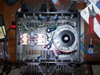
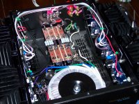
So I have the main power completed and I will do the rest tomorrow, I'm not feeling well.
I'm glad to see this much progress though.
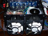
HUGE fans.....!! With any luck, and some high bias, you should be able to get that amp to hover about three inches above your countertop.... 🙂
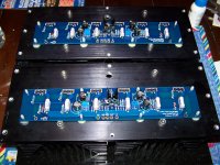
Nice looking construction, and it's coming along well.....!!
So I have the main power completed and I will do the rest tomorrow, I'm not feeling well.
I'm glad to see this much progress though.
Very nice so far! But, I would use a "solid single" wire on the power supply. I would not use speaker wire in any power supply. Maybe I am wrong here!
also I would "twist" better those wires coming in from thermistor (AC LINE) to power switch and push them as far as I can from amp boards and inputs. Again this is just a suggestion, I hope you do not get offended.
Last edited:
@ Lanchile.....
Yes, I will redo those wires, those were in the chassis when I started.
4 bolts and the heatsinks come off so it makes for a very serviceable amp.
I do have concerns about the 18awg speaker wire I'm using for the mains and I don't yet know what I will do.
The high V insulation is overkill for 120V mains and I guess I figured the insulation on the speaker wire was fine for the application.
Good thing I'm not selling this commercially.
@ CanAm....
Those are 120mm fans and I am hoping to bias this at 400mV per device.
Each fan can move just over 50cfm and I will find the happy bias point then I will adjust the fans to get the low noise I'd like.
THAAR SHE BLOWS
Hey fellas, I got this thing heating up the room.
Looks like I need to replace R9 with the 5k that 6L6 suggested.
Right now I have 250mV offset at 145mV bias and I can't bias any higher.
But it looks good.
Hey fellas, I got this thing heating up the room.
Looks like I need to replace R9 with the 5k that 6L6 suggested.
Right now I have 250mV offset at 145mV bias and I can't bias any higher.
But it looks good.
Attachments
Last edited:
On my L channel I have 1.12V DC offset without proper warmup and I can max the trim either way without major change.
My R channel is only 250mV and maxing the trim both ways also won't cause much change.
I will change R9 to 5k but should I look at changing R22 in the event I still can't get the offset to play nice after I bias this thing up higher?
I'll also get the fans going to see if even higher bias is helpful.
- Status
- Not open for further replies.
- Home
- Amplifiers
- Pass Labs
- My F4 Build