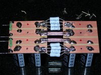
Traffo still holding strong at 18.2VAC at the input of the rectifier, sorry I didn't include that bit.
Here are my voltages.
Line IN - 120VAC
Rect IN - 18.305, 18.305VAC
Rect Out - 21.95, 21.95VDC
Supply Out - 21.35, 21.35VDC
Bias - 350mV per
Line IN - 120VAC
Rect IN - 18.305, 18.305VAC
Rect Out - 21.95, 21.95VDC
Supply Out - 21.35, 21.35VDC
Bias - 350mV per
I'm now became curious, so I measure supply voltages of my J2:
(Because my four channel F4 now not available.)
So:
Trafo secondaries are 18,45VAC (It has four independent secondaries, all of them goes to a similar 35A bridges, and it followed by the four cap banks.)
At the rectifiers DC side I measure 22.8VDC.
22.5VDC passes to the amp board. Plus and minus of course.
So I think its similar to yours.
Last edited:
I'm using Fairchild GBPC3506.
I don't see how it is sag.
My traffo is at 18.3V, that is well within specs and I'm only losing .6V through the CRC.
Since this is all Class A and these are idle readings I just don't see the sag anywhere outside the rectifiers.
Is it possible I have bad rectifiers?
I don't see how it is sag.
My traffo is at 18.3V, that is well within specs and I'm only losing .6V through the CRC.
Since this is all Class A and these are idle readings I just don't see the sag anywhere outside the rectifiers.
Is it possible I have bad rectifiers?
Gyuri...what is your total current?
It only looks like I'm 1V behind you and I'm very heavily biased (@350mV) for an F4.
It only looks like I'm 1V behind you and I'm very heavily biased (@350mV) for an F4.
Last edited:
My 12 FET's are pulling 9A.
All in all though I don't think I'm far enough off to worry about this.
I guess so long as I don't swing to the rails I will be fine.
All in all though I don't think I'm far enough off to worry about this.
I guess so long as I don't swing to the rails I will be fine.
My 12 FET's are pulling 9A.
All in all though I don't think I'm far enough off to worry about this.
I guess so long as I don't swing to the rails I will be fine.
I also thinks so.
18.3V x 1.3 for Class A, yields about 23.5V. Figure in a small amount for drop across CRC and I would bet difference is due to transformer. Antes have shown in some threads slightly more sag. Either way, it should not be a big deal if its not leading to noisey PSU.
Nope, This thing is just WONDERFUL.
I just upped the bias from 300 to 350mV just for kicks.
My highest middle pin temp is only 51C, my fans are doing a fantastic job keeping this thing cool.
I have finally gotten a hold of some 14V Zeners to run each pair of fans from, they are inaudible from 3ft. away.
I just upped the bias from 300 to 350mV just for kicks.
My highest middle pin temp is only 51C, my fans are doing a fantastic job keeping this thing cool.
I have finally gotten a hold of some 14V Zeners to run each pair of fans from, they are inaudible from 3ft. away.
Some what low by data sheet. the bridge should have about 1 to 1.1 volt drop at 12 amps . Thus 18.3 (secondary voltage) times 1.404( square root of 2 to figure peak to rms ) about 25.7 minus 1.1 (forward voltage drop) is about 24.6 approx .
Last edited:
Hi Einric
Thanks for the nice PM !
I have been off the air for a while ...
... but gettin' back into things now.
Nice to hear you like the build & it all went well.
C O O L !
Si.
Thanks for the nice PM !
I have been off the air for a while ...
... but gettin' back into things now.
Nice to hear you like the build & it all went well.
C O O L !
Si.
- Status
- Not open for further replies.
- Home
- Amplifiers
- Pass Labs
- My F4 Build
