Advantages of ESL:
Theoretical distortion is 0, practical distortion is very small yet.
Mebrane of ESL is lighter than Ribbon Laudspeaker, so ESL has excellent transient characteristic.
ESL works on the cool condition.
Shortcomings of ESL:
Moisture sensitive, < 55% of working relative humidity is recommended.
Efficiency is lower.
My diaphragm coating
- Polymer emulsion;
- EC- mechanism of conduction and highly resistive;
- Nontoxic (don't drink it),no special precautions are required;
- Chemically very stable (withstands UVA/B, ozone, biological degradation, will not discolor upon aging );
- Water soluble;
- Easy for use,1:5 or 1:10 diluting is recommended;
- Perfect bonding to Mylar membrane;
- When it dries,it becomes a polymer layer;
- The layer is tough,conductive,and water-repellent;
- Colorless and almost transparent;
- The added weight of the layer could be ignored;
- Flexible;
- The layer has a long time durability (more than ten years at least);
- Shelf-life of around 12 months;
Stator:
- It is a modular design, some basic modules can be combined into a large one;
- In order to minimize idle distributed capacitances between two stators, stators are designed with PCB, so efficiency and high-frequency response of my ESL are improved remarkably;
- Utilizing design of distributed resonances which has more flat frequency response;
- In order to uniformize driving electro-static force on whole surface of membrane, a design of honeycomb structure copper foil on stators is used.
Membrane material
Mylar, thickness: 3.8μm;
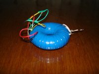
Setup transformer for ESL:
1. Setup is a c-core which is wound from Grain Oriented silicon steel strip and are annealed in high vacuum furnace under protection atmosphere;
2. Multi-sectioned design. Primary winding has 6 sections and secondary winding has 4 (clockwise and anti-clockwise) sections.
3. Excellent frequency and square wave response;
4. Power handling conservatively set at 50 watts continuous;
5. 100:1 turns ratio;
6. Transformers are totally hand wound;
Technical parameters:
Middle ESL:
- Dimension of one unit: 500mm*200mm;
- Spacer: 1.5-2mm thick (Bias Voltage: 2KV/mm);
- Bias Voltage: 3-4 kV (thick of spacer are 1.5-2mm);
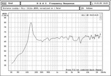
- Frequency response: 200Hz – 30 kHz (see figure -);
- Cross Frequency recommended:
For one panel: Fcut>=400Hz;
For four panels: Fcut>=200Hz;
- Input impedance: 4Ω or 8Ω;
- Driving Power (min. / max.): 2 – 80W (R.M.S.);
- Power supply: ~220V;~110V is selectable;
- Working environment: recommended relative humidity is less than 55%.
Tweeter ESL:
- Dimension of one unit: 350mm*70mm;
- Spacer: 0.5-1mm thick (Bias Voltage: 2KV/mm);
- Bias Voltage: 1-2 kV (thick of spacer are 0.5-1mm);
- Frequency response: 1KHz – 30 KHz (see figure -);
- Cross Frequency recommended: Fcut>=1 - 2KHz;
- Input impedance: 4Ω or 8Ω;
- Driving Power (min. / max.):2 – 20W (R.M.S.);
- Power supply: ~220V;~110V is selectable;
- Working environment: recommended relative humidity is less than 55%.
Theoretical distortion is 0, practical distortion is very small yet.
Mebrane of ESL is lighter than Ribbon Laudspeaker, so ESL has excellent transient characteristic.
ESL works on the cool condition.
Shortcomings of ESL:
Moisture sensitive, < 55% of working relative humidity is recommended.
Efficiency is lower.
My diaphragm coating
- Polymer emulsion;
- EC- mechanism of conduction and highly resistive;
- Nontoxic (don't drink it),no special precautions are required;
- Chemically very stable (withstands UVA/B, ozone, biological degradation, will not discolor upon aging );
- Water soluble;
- Easy for use,1:5 or 1:10 diluting is recommended;
- Perfect bonding to Mylar membrane;
- When it dries,it becomes a polymer layer;
- The layer is tough,conductive,and water-repellent;
- Colorless and almost transparent;
- The added weight of the layer could be ignored;
- Flexible;
- The layer has a long time durability (more than ten years at least);
- Shelf-life of around 12 months;
Stator:
- It is a modular design, some basic modules can be combined into a large one;
- In order to minimize idle distributed capacitances between two stators, stators are designed with PCB, so efficiency and high-frequency response of my ESL are improved remarkably;
- Utilizing design of distributed resonances which has more flat frequency response;
- In order to uniformize driving electro-static force on whole surface of membrane, a design of honeycomb structure copper foil on stators is used.
Membrane material
Mylar, thickness: 3.8μm;
Setup transformer for ESL:
1. Setup is a c-core which is wound from Grain Oriented silicon steel strip and are annealed in high vacuum furnace under protection atmosphere;
2. Multi-sectioned design. Primary winding has 6 sections and secondary winding has 4 (clockwise and anti-clockwise) sections.
3. Excellent frequency and square wave response;
4. Power handling conservatively set at 50 watts continuous;
5. 100:1 turns ratio;
6. Transformers are totally hand wound;
Technical parameters:
Middle ESL:
- Dimension of one unit: 500mm*200mm;
- Spacer: 1.5-2mm thick (Bias Voltage: 2KV/mm);
- Bias Voltage: 3-4 kV (thick of spacer are 1.5-2mm);
- Frequency response: 200Hz – 30 kHz (see figure -);
- Cross Frequency recommended:
For one panel: Fcut>=400Hz;
For four panels: Fcut>=200Hz;
- Input impedance: 4Ω or 8Ω;
- Driving Power (min. / max.): 2 – 80W (R.M.S.);
- Power supply: ~220V;~110V is selectable;
- Working environment: recommended relative humidity is less than 55%.
Tweeter ESL:
- Dimension of one unit: 350mm*70mm;
- Spacer: 0.5-1mm thick (Bias Voltage: 2KV/mm);
- Bias Voltage: 1-2 kV (thick of spacer are 0.5-1mm);
- Frequency response: 1KHz – 30 KHz (see figure -);
- Cross Frequency recommended: Fcut>=1 - 2KHz;
- Input impedance: 4Ω or 8Ω;
- Driving Power (min. / max.):2 – 20W (R.M.S.);
- Power supply: ~220V;~110V is selectable;
- Working environment: recommended relative humidity is less than 55%.
Looks like advertisment to me... so goes the mass production...
In that case: something made by hand is good in paintings and other arts.
In respect to mass produced amplifiers/transformers/encasing frames etc. everything made my CNC or other machine is usually better due to absence of human errors. Hand wound transformer is good if no other means are on avail. Unless some wierd winding sequence is used machine wound one is better or closer if you'd like to design.
Hand made is expensive if done by qualified staff.
If it's this way not for the artistic/personal expression reasons - there are at least two types of Chineese products: exellent and worthless...


there are at least two types of Chineese products: exellent and worthless...
Zhigang's must be the excellent one huh ? ...😀 More pics Zhigang.................
Last edited:
Hey Zhigang.
Looking great, cant wait to see the finished units and get a sound report 🙂
Can you share with us more about the polymer emulsion for the coating. What do you recommend?
Cheers
Dean
Looking great, cant wait to see the finished units and get a sound report 🙂
Can you share with us more about the polymer emulsion for the coating. What do you recommend?
Cheers
Dean
alexberg : Looks like advertisment to me...
Sorry, I’m a audiophile and retired electronics engineer, and not a businessman. I build ESL for hobby, not for money.
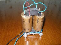
Pic. of set-up trans. Is following:
Sure, that's where hands become handy🙂
Waiting for pics
P.S. CNC for making frame etc. is even more handy
Hi Zhigang324,
It's good to know that you are making your ESL for hobby and not for money. Can you share with us more information on how you build your ESL? You've stated that your stators are made of PCB, do you do sectioning on your stators? Do you put a lot of rivets in order to keep the stators together? Do you mind sharing with us how you make your coating material?
Wachara C.
reply
O-core set-up Trans.
1. O-core is wound from one continuous silicon steel strip and there are no joints;
2. The round cross-section improves electric performance of the core. The tight windings and the fact of no shape angles provide a well-distributed magnetic field. The improved coupling reduce magnetic leakage.
Maybe O-core set-up Trans. Is the best one.
But winding O-core set-up trans. is very very difficult by hand.
Attachments
O-core set-up Trans.
O-core is wound from one continuous silicon steel strip and there are no joints
SKIPPED
But winding O-core set-up trans. is very very difficult by hand.
1. Wire resistor is made of continious metal rod and there are no joints
2. Round core is better then square one. Yes, in 1MW tranny where winding is done from copper "two-by-fours".
Otherwise all the x-formers would of utilize round cores. One nation sells qubic watermellons as well...
Are you kidding me?
Toroids are much easier to wind BY HAND.
I would love to see C core wound by hand, without primitive winch.
Last edited:
He meant that the O-core are wound from continuous steel strips without air gap (unlike C-core).
There are many who use O-core instead of rectangular-section toroids for audio, and I suppose for good reasons.
The gentleman, whoever he is and where ever he comes from, merely showed us some pictures of his work.
Even if you do not like it or think it is primitive, or that his English is not native, he still deserves our respect.
Better still, why not open a new thread and show us your wonderful work.
Best regards,
Patrick
Last edited:
reply
Are you kidding me?
Toroids are much easier to wind BY HAND.
A set-up trans. for ESL isn’t a power trans. In order to minimize leakage inductance and distributed capacitance, an excellent set-up trans. is very complicated, it is a multi-sectioned design, primary winding has 6 sections or more and secondary winding has 4 or more (clockwise and anti-clockwise) sections. It isn't as simple as you might think.
I think you meant "step-up" transformer.
It multiplies the low voltage output of an "ordinary" power amplifier to the high voltage required to drive the ESL membrane.
What is the step-up ratio of your transformer ? 1:150 ?
How about primary and secondary inductances, leakage inductance, interwinding capacitance, DC resistances, ....., etc. ?
Patrick
Hand made x-former
R-CORE is prety much steel equivalent to "Image is everything, thirst is nothing" (c) "Coca-Cola" "Sprite"
What's clear on picture posted is well defined single wire primary with low turns count, wound on top of secondary(ies).
I may be mistaken, but no multiple terminations intrinsic to sectioned/interlieaved designs are visible - you can't really hide a lot of interconnections in toroids - they create nice buldges😉.
So far as simple as use of standard transformer with hand wound seconday form hookup! wire, used by some DIYers here.
Making/designing transormers for more then 20 years by now I would say that using standard steel toroids for really good ESL transformer is not way to go.
For those who can't do it Calvin suggested readily available 50/60 Hz x-formers for power supplies, same as above.
What's below is well known, but rarely used in industry - hard to automate.
Due to high magnetization current you'll end up with rather high turns count in order to minimize one.
Smart and elegant design with minimal capacitance and decent coupling would be so-called cable transformer with high iron cross-section.
Metglas of similar material shall be used, having magnetizing current 10-20 times lower.
How can it be so better - increasing core cross section 10 times you'll lower the turns 10 times, so resistance is lower as well as stray capacitance.
Cable transformers are known for relatively high coupling, especially if winding thickness is low (easily achievable) - low stray inductance as well.
So win and win and win.
How can it be done.
1. Easy way - look for Finnish ESL DIY site. Rather long stack of EE cores, foil primary, wire secondary. Result looks like a beam.
2. Hard way - stacked toroids. Keeping in mind Finn design, you'll wind secondary on each core, then stack them together on top of each other, insulate, wind primary.
Result looks like a sausage. Primaries seems to be connected in series - please do not elaborate on this.
3. Really hard way, insulation problems, (the best) - wind primary and secondary on each core, connect primaries in parallel, secondaries in series.
Do not forget that at the hot end voltage applied between windings is the highest.
Advantage of #3 is that you exclude frontal parts of secondary winding from magnetic leakage, which happens in case #2 where those parts are not in proximity with primary.
Again all of the above is in books... just look for high voltage transformer design.
Alex
P.S. R-cores should of have better yeild due to absence of corners and lesser damage to wire while winding by machine.
Additional milling operation and waste of material makes it cost prohibitive like qubic watermelons.
Would a foil primary not create much more interwinding capacitance than a single wire primary ?
Thanks for the technical input for Tx design,
Patrick
Thanks for the technical input for Tx design,
Patrick
reply
Do you mind sharing with us how you make your coating material?
ESL coating material is researched independently by myself, it is different from another coating materals, and the producing technology was very simple. Because ESL coating is core technology of ESL, and refered to too much commercial benefit (All Manufacturer factories of ESL in China have no breakthrough on coating materials, so they are hard up for coating technology ), I’m very sorry that I could’t share the detail about the coating materil with all of you.
I do not know what exactly Arto's Kolinummi design is,Would a foil primary not create much more interwinding capacitance than a single wire primary ?
Thanks for the technical input for Tx design,
Patrick
but looking at picture and params (weight, dims) on his site following may apply:
Cores 16x52x70 (double C or EE) 8 sets
Primary around 50 turns (foil, author preference)
center tapped secondary 2х1500.
In regard to capacitance:
Nomnal secondary load is 10nF, multiplied by (3000/50)^2 -> 36 microfarads @ primary.
I would bet that foil coil capcitance ever comes even close to that number.
Alex
reply
Strucure and connection of set-up trans. ( C-core or O-core):
Primary windings: 1-1, 3-1, 5-1; 1-2, 3-2, 5-2; all have clockwise 40turns and connected in parallel.
Secondary winding: 2-1, 4-1; 2-2, 4-2. All have 1000 turns. 2-1 and 4-2 are clockwise; but 2-2 and 4-1 are anticlockwise.
Transformer ratio is 1:100
Attachments

Advantages of ESL:
My diaphragm coating
- Polymer emulsion;
- EC- mechanism of conduction and highly resistive;
- Nontoxic (don't drink it),no special precautions are required;
- Chemically very stable (withstands UVA/B, ozone, biological degradation, will not discolor upon aging );
- Water soluble;
- Easy for use,1:5 or 1:10 diluting is recommended;
- Perfect bonding to Mylar membrane;
- When it dries,it becomes a polymer layer;
- The layer is tough,conductive,and water-repellent;
- Colorless and almost transparent;
- The added weight of the layer could be ignored;
- Flexible;
- The layer has a long time durability (more than ten years at least);
- Shelf-life of around 12 months;
😉about 6 sentences are literally copied from my spec.sheet (EC-coating), another two of them are slightly adapted. I am flattered
- Status
- Not open for further replies.
- Home
- Loudspeakers
- Planars & Exotics
- My ESL experience