Indeed !!!
But I guess your chemical formula is less easy to copy, and you probably had not / would not ship any to China.
😉
Patrick
But I guess your chemical formula is less easy to copy, and you probably had not / would not ship any to China.
😉
Patrick
Sorry can't hold it... that's why I would not describe some things here...Advantages of ESL:
My diaphragm coating
Skipped
😉about 6 sentences are literally copied from my spec.sheet (EC-coating), another two of them are slightly adapted. I am flattered
That's the point - some (I hate to say chineese manufacturers?!) as well as DIYers can definetely replicate thingies described here (as well as words).
reply
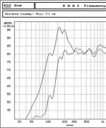
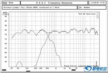
Suppressing the resonance peak in the lower frequency:
A 10μF CBB capacity is connected in series with primary winding of set-up trans.. High-pass filter consisted of the C and inductance of primary winding of set-up trans. makes frequency response in the lower frequency become flat.
Suppressing the resonance peak in the lower frequency:
A 10μF CBB capacity is connected in series with primary winding of set-up trans.. High-pass filter consisted of the C and inductance of primary winding of set-up trans. makes frequency response in the lower frequency become flat.
Attachments
Suppressing the resonance peak in the lower frequency:
A 10μF CBB capacity is connected in series with primary winding of set-up trans.. High-pass filter consisted of the C and inductance of primary winding of set-up trans. makes frequency response in the lower frequency become flat.
Hello zhigzng324,
Using the inductance of the primary winding of the step-up transformer as part of the HP crossover is generally not the best idea.
The reason is that the inductance of the primary is a function of the permeability of the transformer core which changes with flux density as the signal input varies in amplitude. Inductance of the primary usually varies by more than a factor of 3 with typical input voltages. Inductance increases with input voltage until core saturation is reached. Increasing voltage beyond this point and the inductance decreases abruptly as the core saturates.
Try measuring the frequency response at 10 different volume settings from 1Vrms to 28Vrms. You will see the response of your HP crossover network is dependent on volume setting.
The easiest way to avoid this problem is to swamp the varying primary inductance with a lower value air core inductor and/or resistor.
Here is an example crossover design Calvin posted in which he used a resistor to linearize the primary inductance.
http://www.diyaudio.com/forums/planars-exotics/64620-ping-calvin.html#post727647
Last edited:
reply
Hi, alexberg:
Maybe you and me are in the same way in expression about optimum ESL coating material, but that is no significance, more important is coating material itself, I have never met with you, and I don't even know who you are, so I could not get technical know-how - chemical formulation from you or other ESL manufacturers. Actually I have R&D my own ESL coating materials independently in 1996. Today my earliest ESLs are still in good condition, so I could say that the working life of my coating material for at least 10 years.
I’m sorry for bad English!
There is nothing wrong with your English, so I also do not believe it is misunderstanding caused by the language barrier.
But it is hard to believe that 2 person from two nationalities and both being non-native speakers would describe a coating with exactly the same wordings by pure coincidence !!!
Patrick
But it is hard to believe that 2 person from two nationalities and both being non-native speakers would describe a coating with exactly the same wordings by pure coincidence !!!
Patrick
Hi, alexberg:
Maybe you and me are in the same way in expression about optimum ESL coating material, but that is no significance, more important is coating material itself, I have never met with you, and I don't even know who you are, so I could not get technical know-how - chemical formulation from you or other ESL manufacturers. Actually I have R&D my own ESL coating materials independently in 1996. Today my earliest ESLs are still in good condition, so I could say that the working life of my coating material for at least 10 years.
I’m sorry for bad English!
Zhigang,
I am the person from who you literally copied most of the sentences of my specsheet.
To you this is, and I qoute, of no significance.
Actually you are confirming the chinese stereotype of careless disrespecting intellectual property. Except of course from the more 'difficult' parts like the exact added mass, which is subjectively described and conflicts with the proclaimed R&D.
In future, it would be better to make at least a reference to the person from you are copying. This would also considerably improve the credibility of all of your claims.
Last edited:
Martin Jan,
I agree with you there are a lot of black sheeps in China.
And they copy not only overseas IPs but also Chinese ones, including state owned companies copying industrial products from private companies 1:1.
But at the same time, more than 90% of the Chinese population in this planet still respect IPs of other people. Not a small population owns a large IP portfolio in Silicon Valley, for example.
And it is all too easy to catergorise people by race or ethnic identity, as I am sure you know in the Netherlands.
Patrick
Last edited:
Zhigang,
I am the person from who you literally copied most of the sentences of my specsheet.
snip
Perhaps I missed something here. But that's quite a severe accusation. Can you support it for all of us to see?
Ben
Why did Zhigang 'made' such elaborate story about a coating:
- which is not, and has never been, offered for sale to the DIY community
- which can't be made at home because Zhigang doesn't reveal the composition as he is afraid some chinese commercial entities might perform a similar copy-paste trick.
??
Assuming some personal motivations behind the purpose of his story I couldn't resist in mentioning the fact that most of my sentences of my spec. sheet were inserted in his story as already confirmed by others. This would be the end of story as I've written down what needs to be written down, the DIY community would understand and I definately need NOT any comments from Zhigang himself.
However Zhigang himself put away the issue away being irrelevant while corresponding with another forum member (!). I didn't like that. Think it is not true either, so I made some statement about his behaviour and the credibility of his R&D bla-bla.
I have no intention to discriminate. I have no hard feelings against any chinese or Zhigang in particular.
- end of story-
reply
Hi,bolserst:
You are right. Because of nonlinearity of iron core, a H.P. Filter which uses the inductance of primary winding of set-up trans. isn’t a good choice that is my earlier design. In my latest design a fourth- order zero-phase active filters are used, but it is a work in progress yet.
Hi,bolserst:
You are right. Because of nonlinearity of iron core, a H.P. Filter which uses the inductance of primary winding of set-up trans. isn’t a good choice that is my earlier design. In my latest design a fourth- order zero-phase active filters are used, but it is a work in progress yet.
Question:
how much more trouble is it to simply do it the right way, direct high voltage amp like the Sanders approach?
With the depth, effort, and obvious motivation shown ESLs in the forum and this thread, why not just create a HV amp or some kind of add-on HV stage?
Can't be much more trouble than designing and winding your own transformers.
I used such an amp for 15 years and worked great. Substantial practical obstacles due to having to wear rubber-soled shoes and locking the kids out of the music room (kidding).
reply
Pardon me for speaking frankly:
Some people make a mystery of coating material for ESL. In fact it is nothing but a kind of conducting polymers! If you have knowledge about chemistry, you should have many options for coating material for ESL, such as me.
Pardon me for speaking frankly:
Some people make a mystery of coating material for ESL. In fact it is nothing but a kind of conducting polymers! If you have knowledge about chemistry, you should have many options for coating material for ESL, such as me.
reply
Hi,bentoronto:
I completely agree with your point of view: using H.V. Amp. which drives ESL directly is the best solution, but a driving voltage of 4000Vp-p is needed for full- range ESL, to build such H.V. Amp. maybe is a big challenge. I have built a 1000Vp-p H.V. Amp. which can be used to drive ESL tweeter or electrostatic earphone only.
Hi,
...only best in theory. Practical aspects hinder most designs to perform as well as a good tranny. If You use a good combination of panel, tranny and capable amp there´s hardly any chance of bettering things with an conceptually inferior HV-design. The voltage range alone is a challenge. 1.000V-pp (350Vrms) is good only for small panels and Headphones with d/s of less than 1mm. 4.000Vpp (1.4kVrms) is just enough for less than 2mm d/s, which is the value for a midrange or Hybrid-panel. FRs with typically >2mm d/s require much more voltage, think of 10.000Vpp and more.
It is to understand, that a well designed and sounding HV-amp
- must be designed to the needs of the panel. There´s no OneFitsAll.
- is extremly inefficient if running in class A
- hardly reaches or even exceeds a power bandwidth limit of 20kHz. So there´s a chance of nasty sounding current clipping
- that known designs like the slightly less inefficient SRPP-like Acoustat rely very low idle currents, massive feedback and multiple compensation because of serious inherent non-linearity. If a lowvoltage amp were designed like that, no one would even think it could cope sonically with a decently designed amp. Why should such an amp sound better working into a speaker load that´s as failor revealing as none else?
- a well designed tranny can be very low in distortion. So low indeed that a amplifier working into the very complex capacitive load has a hard time to equal that.
- like a tranny every panel needed a dedicated amp, designed for the special demands of this panel
- it means increased complexity and cost.
- at last.. safety reasons. Not many have designed with HV. Support via forum is less broad and maybe even less ´qualified´ compared with other thread-themes. The chances of ´redoing´ things is seriously reduced compared to working with +-15V-designs. AFAIk heaven and hell are not running on 115/230V power lines 🙂 A tranny is already a potentially lethal device if touched while running. A HV-amp is even more dangerous -and at one point You need to fire up the thing, setting and controlling bias values etc.
I tested my panels with different trannies and 2 different HV-amps, one a SE-style class-A no NFB design, the other a SRPP-style low idle current class-AB FB design. The ranking was that the SE -class A and the best trannies performed quite on par with the trannies allowing for a larger dynamic range. The second amp sounded just as any cheap class-AB feedback design like HiFi, not like music.
Now thats a matter of personal taste and surely not cast in granit, but who else has done such a comparison using first class examples of both technologies?
The amp-theme might become more interesting in future with the upcoming of new power devices in SIC-technology (there are some highly interesting N-channel HV-Power-JFETs in the pipeline, which might even work as some spectacular devices for lowvoltage amps).
But still such amps would need to proove any better in performance than the best trannies, otherwise there would be no sense to it. A difficult aim indeed.
jauu
Calvin
Last edited:
Hi,bentoronto:
I completely agree with your point of view: using H.V. Amp. which drives ESL directly is the best solution, but a driving voltage of 4000Vp-p is needed for full- range ESL, to build such H.V. Amp. maybe is a big challenge. I have built a 1000Vp-p H.V. Amp. which can be used to drive ESL tweeter or electrostatic earphone only.
Great. Two of us agree on what is the best solution. Thanks.
Here is information. The purpose is to provide some people with some rough picture of voltage levels.
I can't speak for Sanders' design, but I was essentially driving a little army of resistors - a very simple and clean load - but hot. The speakers were parallel across the resistors and the amp hardly knew the ESL speakers were there.
About voltages, I was driving Dayton-Wright panels which have quite large spacing between stators (can anybody tell us???) because they can play very loud, and can run on thousands of volts bias (even without the 12kv bias possible with welding gas). I drove panels that were about 6-8 square feet per side.
For 150-3500 Hz, with a B+ of 2400 volts and signal output of maybe 700 or so vrms (I am poor at measuring high voltages and poor memory now), they would play quite loud in a large space of maybe 350-450 sq feet.
Loud but not 100 dB impress-your-friends levels. Certainly the sweetest sound I ever made.
All the high voltage gear and wiring was below the floor, in the cellar. When I moved, it wasn't possible to keep the wiring away from humans and so I went back to the 80 lbs Dayton-Wright matching transformer box.
Hi,
reminds me of the saying: "Billions of flies can´t be wrong....eat ****!" 😀
Everyone can have or agree on an opinion....but that dosen´t increase thats value or the degree of truth in it.
Sander´s amp had a chain of resistors as plate load. The ESL was connected between both legs of the amplifier-bridge.
Without ESL a plate resistor is indeed the easiest load, since no variation in impedance and no phaseshift occurs.
With the ESL between the two amp legs (the same holds btw. true for SE-ESLs with just one amplifier leg) things change though. The load impedance becomes complex and its character is to a great deal due to the ESL. The higher the frequency gets and the more the impedance value of the ESL drops the more does the combined load of ESL and resistor ´look´ like the ESL alone to the amp. It´s too the highfrequency range where besides voltage needs the current demands and hence power demands increase. So the load is in no way an easy load. The impression of: "...the amp hardly knew the ESL speakers were there." might subjectively appear so, factually this is not the case.
It has proven to be good use that an amplifier should still run well within its limits when the speaker reaches its limits. This means a certain headroom voltage-, current- and powerwise. The demands of the ESL are easily calculated by the ESLs parameters and the voltage-breakdown treshold of air. As a rule of thumb for the voltage demand You can calculate app. 1kVrms (~3kVpp) for every 1mm of d/s. This shows, that with high d/s values the required voltages quickly reach impractical high values.
The current needed to drive a sinusodial signal into a capacitive load calculates to I=C*pi*f*Vpp. The formula shows the increasing current demand with rising frequency.
If one decides for lower values than those calculated it might be perfectly ok on a personal level, but one should possibly not talk of a good or even superior design or the ´best solution´. 😎
And we haven´t even started talking about the signal current´s phaseshift against the signal voltage which reduces the phase reserve of the amp, puts additional power- and heat-stress on the output devices and even may lead to oscillations.
jauu
Calvin
Last edited:
Hi,
reminds me of the saying: "Billions of flies can´t be wrong....eat ****!" 😀
Everyone can have or agree on an opinion....but that dosen´t increase thats value or the degree of truth in it..... The impression of: "...the amp hardly knew the ESL speakers were there." might subjectively appear so, factually this is not the case....with high d/s values the required voltages quickly reach impractical high values. snip
jauu
Calvin
Pretty strong imagery about "eat****" you are applying to my opinion based on many years of experience. Good thing I would never dare say that back to you. Where are the Moderators!
As comprehensively authoritative and terminal-beyond-debate as your judgment about my amp is, don't you think it might conceivably be just a tiny bit more authoritative if you actually knew what the load resistors were, the capacitance of the Dayton-Wright panels (or even how many I was driving), the frequency range.... and lots more?
By the way, Calvin, did you actually do the math? Or are you just like those flies that "eat****"?
Last edited:
Hi,
Oh Ben, oh Ben... *lol*
My first sentence in the first reply read: "...only best in theory. Practical aspects hinder most designs to perform as well as a good tranny."
There´s nothing offensive about that, I think, especially because it´s backed up by the following argumentation.
Your reply on that suggested that, since two of You think of the amp solution as best and me saying that ´this is not necessarily so´, that You two are right simply because of a 2:1 score of opinions. But this is certainly no question of a 2:1 or even 1000:1 score. Good technical design is no matter of opinion, gaming or political electioning, but the application of certain design rules and facts.
That´s why I -in a humorous intention as I might add and the attached smiley suggests- brought this little Ridicule about the Flies.
Unfortunately I couldn´t read anything in Your reply that backs up Your opinion with facts. It remains also unclear what ´years of experience´ means. If this experience is about just one particular amp and one or just a few trannies it´d hardly qualify for a general statement. Nor does my -also limited- experience qualify for that. But at least did I analyze and test different amp-topologies and trannies and certainly know the numbers and the maths behind. I surely won´t argue with You about personal tastes. So please stick to facts that back up Your opinion and everything is fine. Then we may discuss the pros and cons to a good use.
jauu
Calvin
- Status
- Not open for further replies.
- Home
- Loudspeakers
- Planars & Exotics
- My ESL experience