Good
Start with powersupply unhooked.
Slowly bring up to full value makeing sure it is stable.
Please post the Vdc from + to G and then - to G and then + to -
Unless someone has a better idea, I would like to start at the begining working to out puts.
Start with powersupply unhooked.
Slowly bring up to full value makeing sure it is stable.
Please post the Vdc from + to G and then - to G and then + to -
Unless someone has a better idea, I would like to start at the begining working to out puts.
Without load the psu dilivers
-54+54vdc.With pcbs connected for up to-5+5vdc I get 2,5vdc at speaker terminals.
-54+54vdc.With pcbs connected for up to-5+5vdc I get 2,5vdc at speaker terminals.
Un hook the big mosfets from the main board and read the voltage drop across the mpsa,s C and E and post voltage
Yes. I think your output fets 1 or more are shot.
Let's make sure the main boards are ok then find what killed you outputs
Let's make sure the main boards are ok then find what killed you outputs
Make sure that C of the 18 for the CCS is tied to the 1.5K and 1nF and gate drive on your board.
Mpsa18 data sheat says... Flat side facing you, left most pin is Emitter.
Mpsa18 data sheat says... Flat side facing you, left most pin is Emitter.
I think just the ccs 18 is done for. But don't change it yet we gotta figure out why it got zapped or if somthing else is wrong.
Check the voltage drop across the 221 ohm res feeding the drain of the ccs 4 the irf9610
Check the voltage drop across the 221 ohm res feeding the drain of the ccs 4 the irf9610
Karajak, that is great news! I bought a very similar looking variac: with a 20amp fuse, 110v. It should come in before the weekend, exactly in time for when I return from my business trip.
We will have to meet up in Greece and have a nice drink, listening to some good music. Your views are a true one of a kind! I can't believe that. My wife loves history, she will be very impressed when I show her that picture.
We will have to meet up in Greece and have a nice drink, listening to some good music. Your views are a true one of a kind! I can't believe that. My wife loves history, she will be very impressed when I show her that picture.
No I can't. I can't see the traces.
Do you have a scematic with R#'s on it?
If you do, share it with me it. It will help.
I'm going off of the diagram off KK's web site with no numbers.
Do you have a scematic with R#'s on it?
If you do, share it with me it. It will help.
I'm going off of the diagram off KK's web site with no numbers.
Sure no problem.
As long as we are on same page.
And I would like to say don't thank me yet. Ill do everything I can. But no promises that it won't end up over my head.
But allot of people here can take over. Or if they see somthing I miss I hope they chime in!
As long as we are on same page.
And I would like to say don't thank me yet. Ill do everything I can. But no promises that it won't end up over my head.
But allot of people here can take over. Or if they see somthing I miss I hope they chime in!
My variac is underway and will arrive on Friday.
Here are the notes that I have taken so far, correct me if I'm wrong:
1) Start with powersupply unhooked.
Slowly bring up to full value makeing sure it is stable.
Please post the Vdc from + to G and then - to G and then + to -
Unless someone has a better idea, I would like to start at the begining
Answer: I did this, I will do it again, but I believe my values are +50.1 - 0 -50.1V
2) Unhook the big mosfets from the main board and read the voltage drop across the mpsa,s C and E and post voltage
Question: Do I need to put the variac at full 110V?
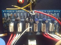
I will also check to make sure my MPA;s are installed withe the flat side to the inside of the board (according to the photo).
3) Check the voltage drop across the 221 ohm res feeding the drain of the ccs 4 the irf9610.
Question: Do I need to put heatsinks on the IRF's as shown on the photo from karajak?
Fun stuff. Quite frankly I was quadruple careful during construction since I knew that if it wasn't right I would most likely not be able to troubleshoot it.. But here we are, let's make the best of it! I'm glad we are in the same boat Karajak!
Here are the notes that I have taken so far, correct me if I'm wrong:
1) Start with powersupply unhooked.
Slowly bring up to full value makeing sure it is stable.
Please post the Vdc from + to G and then - to G and then + to -
Unless someone has a better idea, I would like to start at the begining
Answer: I did this, I will do it again, but I believe my values are +50.1 - 0 -50.1V
2) Unhook the big mosfets from the main board and read the voltage drop across the mpsa,s C and E and post voltage
Question: Do I need to put the variac at full 110V?
I will also check to make sure my MPA;s are installed withe the flat side to the inside of the board (according to the photo).
3) Check the voltage drop across the 221 ohm res feeding the drain of the ccs 4 the irf9610.
Question: Do I need to put heatsinks on the IRF's as shown on the photo from karajak?
Fun stuff. Quite frankly I was quadruple careful during construction since I knew that if it wasn't right I would most likely not be able to troubleshoot it.. But here we are, let's make the best of it! I'm glad we are in the same boat Karajak!

My variac is underway and will arrive on Friday.
cool
Answer: I did this, I will do it again, but I believe my values are +50.1 - 0 -50.1V
maybe double check it, just in case. who knows coulda got fried when you tryed it before.
2) Unhook the big mosfets from the main board and read the voltage drop across the mpsa,s C and E and post voltage
i mean unhook the 4 wires from the main board to fet boards. proably best to do it at the main board. dont unsolder all the fets sorry.
Question: Do I need to put the variac at full 110V?
slowly work up to it with your meter reading the power supply.
then hook up to the main board and do the same.
I will also check to make sure my MPA;s are installed withe the flat side to the inside of the board (according to the photo).
ok, thats good, but thats not the thing we are looking for.
somtimes boards are misslabled. i just want to rule that out. you want to make sure the 18 is in the cir right.
Check the voltage drop across the 221 ohm res feeding the drain of the ccs 4 the irf9610.
Question: Do I need to put heatsinks on the IRF's as shown on the photo from karajak?
need to......no.
you have three mosfets in the front end.
1 is a constant current for the other 2.
it allows a set amount of current to be passed for the other two no matter what.
it gets hotter than the differrental pair, they dont get as hot beucase they share the current from the first. they have half the current.
but fets change their paramters with temp. and since you go to all the effort to match the diff pair its a good idea to put them together thermaly, you dont want 1 to be 50deg and have a Votage potental from gate to soarce of 1v and have the other at 51deg with a Vgs of 1.5vdc....
so, no dont need to. here is what i did diff pair on a short peice of 1/2" by 3/4" al bar stock keeping them ele isolated. and put a small sink on the ccs cause i wanted to keep it cool.
your call isnt going to hurt either way.
- Status
- Not open for further replies.
- Home
- Amplifiers
- Pass Labs
- My Dream Aleph 2 Coming True