Quick comments in no particular order (I am supposed to be helping test a Beat release...)
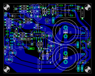
-Can you move the trace (R1-ZD1-C11) a little to the left, then twist C6 clockwise and align it with C11. You might have a little more room for R4 and J3 pads that way.
-Keep in mind that insulated Fastons are fairly wide, and will probably bump into the components near them, specifically C3 and C8, B1, and the relay.
-Looks like you are planning on using a vertical (radial) cement power resistor(?). I think it would be a good use of space if you are looking for a small board.
-Probably a little late to change, but you could use the Panasonic mini metal film resistors. Not very expensive and very small. Could give you some more flexibility in layout.
BrianDonegan said:Quick comments in no particular order (I am supposed to be helping test a Beat release...)
-Can you move the trace (R1-ZD1-C11) a little to the left, then twist C6 clockwise and align it with C11. You might have a little more room for R4 and J3 pads that way.
-Keep in mind that insulated Fastons are fairly wide, and will probably bump into the components near them, specifically C3 and C8, B1, and the relay.
-Looks like you are planning on using a vertical (radial) cement power resistor(?). I think it would be a good use of space if you are looking for a small board.
-Probably a little late to change, but you could use the Panasonic mini metal film resistors. Not very expensive and very small. Could give you some more flexibility in layout.
1) OK, sounds good.
2) Yes, valid concern, but I measured and they should be OK.
3) Yes, I have some of those, and I thought they fit well.
4) Hmmm, hadn't considered it, since I already have all the metal film reistors I need in the standard size... I think it may be best left that way to keep it more flexible, since you can always use a smaller leaded part in a bigger space, but its harder to do the opposite.
My 2 cents
Shift C1 & C2 down and to the right. They could also be brought into symmetry (forgive my analysis).
This provides "working" room for R2 & C4.
Following in the path of Brian about C6; R39, R43 & C34 can be shifted left, providing more room for traces (with a longer J3).
Have you limited the area on the heatsink side of the LM3886 for heatsink mounting?
Re: My 2 cents
Ok Bg,
Did you see my last post? I shifted the things around C6 to the left a bit, and as it is now there is plenty of clearnace between everything, but I will work on it some more tomorrow.
As far as C1 and C2 I will see what I can do there, there is only so much I can do based on where I need to run the power traces.
You are saying you would like pads for smaller C3/C8? That would have to result in a pretty significant circuit alteration (what are thinking like 1500uf?) I would think, but hey, I have no objection to seeing how it looks. Wouldn't 7.5mm be reasonable?
Great ideas so far people. I will see what I can do.
bg40403 said:Shift C1 & C2 down and to the right. They could also be brought into symmetry (forgive my analysis).
This provides "working" room for R2 & C4.
Following in the path of Brian about C6; R39, R43 & C34 can be shifted left, providing more room for traces (with a longer J3).
Have you limited the area on the heatsink side of the LM3886 for heatsink mounting?
bg40403 said:Could we have pads on the PSU legs for a small (5mm space) poly bypass cap?
Ok Bg,
Did you see my last post? I shifted the things around C6 to the left a bit, and as it is now there is plenty of clearnace between everything, but I will work on it some more tomorrow.
As far as C1 and C2 I will see what I can do there, there is only so much I can do based on where I need to run the power traces.
You are saying you would like pads for smaller C3/C8? That would have to result in a pretty significant circuit alteration (what are thinking like 1500uf?) I would think, but hey, I have no objection to seeing how it looks. Wouldn't 7.5mm be reasonable?
Great ideas so far people. I will see what I can do.
Re: My 2 cents
Not sure what you mean here. I have it so the LM3886 will sit flush against the heatsink when the pcb is touching the heatsink. There is no "extra" PCB behind the LM3886 like the REV A boards have. I would be glad to add it if you think it's a cool feature. It does make the board very stable on the heatsink when you place in a slot.
bg40403 said:Have you limited the area on the heatsink side of the LM3886 for heatsink mounting?
Not sure what you mean here. I have it so the LM3886 will sit flush against the heatsink when the pcb is touching the heatsink. There is no "extra" PCB behind the LM3886 like the REV A boards have. I would be glad to add it if you think it's a cool feature. It does make the board very stable on the heatsink when you place in a slot.
18 or 25v Tranny?
I found a mob that has a good range of toroids on their website, prices are equivalent to others. I have a choice!
I'm thinking of a 300VA for my Mauro, but I can't decide between 18 or 25V. From the specs, it looks like the 25v would deliver a few more watts - I'm wondering if that means a lot more heat dissipation on the heatsink as well?
Here's the 25v tranny
Michael
You will be fine with the 25V trafo. The 18 is really pushing the low side. 21 would be OK, but I would stick with 24-25 secondaries.
I was using a 160VA 22v tranny before the one I am using now. Still sounded great, but didn't really give it a workout.
-b
-b
Steve @ Apex.jr sells some great transformers for gainclones that should also work for this also.
I am still sitting on the fence about building one of these. I think the design is VERY nice, but I have built WAY too many CG's as is.
Is the character of this amp significantly different from the LM3886 alone?
I am still sitting on the fence about building one of these. I think the design is VERY nice, but I have built WAY too many CG's as is.
Is the character of this amp significantly different from the LM3886 alone?
rabstg said:Steve @ Apex.jr sells some great transformers for gainclones that should also work for this also.
I am still sitting on the fence about building one of these. I think the design is VERY nice, but I have built WAY too many CG's as is.
Is the character of this amp significantly different from the LM3886 alone?
In a word. YES
Sonics
Troy,
I lost the Krell clone thread about 2500 posts back. How did it work out for you sonically? Did it end up a lot better than your GC's? My four boards still wait to be stuffed.
I am sitting off 635 and Coit stuffing a rev a board tonight. Hope to drill the boxes this weekend and be listening by Monday.
George
rabstg said:Steve @ Apex.jr sells some great transformers for gainclones that should also work for this also.
I am still sitting on the fence about building one of these. I think the design is VERY nice, but I have built WAY too many CG's as is.
Is the character of this amp significantly different from the LM3886 alone?
Troy,
I lost the Krell clone thread about 2500 posts back. How did it work out for you sonically? Did it end up a lot better than your GC's? My four boards still wait to be stuffed.
I am sitting off 635 and Coit stuffing a rev a board tonight. Hope to drill the boxes this weekend and be listening by Monday.
George
Re: Sonics
Well they are doing a second run or PCB's now, and this was my last post:
http://www.diyaudio.com/forums/showthread.php?postid=691075#post691075
Guess how far I've gotten on building....
Panelhead said:Troy,
I lost the Krell clone thread about 2500 posts back. How did it work out for you sonically? Did it end up a lot better than your GC's? My four boards still wait to be stuffed.
I am sitting off 635 and Coit stuffing a rev a board tonight. Hope to drill the boxes this weekend and be listening by Monday.
George
Well they are doing a second run or PCB's now, and this was my last post:
http://www.diyaudio.com/forums/showthread.php?postid=691075#post691075
Guess how far I've gotten on building....
Input section question.
Stuffed 75% of a Rev A board last night. Found my 1/2 watt HoThislco resistors will not fit in the holes so I am off to find some generic 1/4 watt.
I am thinking about bypassing the input capacitor. My preamp is transformer coupled, it cannot pass dc. The small value cp across the input of the LM318 makes me wonder if no input cap will upset the operation of the circuit.
Should I leave well enough alone and stick with the input capactors?
I really like the quality of the boards. Look foeward to hearing what this amp can do.
George
Re: Input section question.
I would leave the coupling cap. But thats just me. 🙂Panelhead said:Stuffed 75% of a Rev A board last night. Found my 1/2 watt HoThislco resistors will not fit in the holes so I am off to find some generic 1/4 watt.
I am thinking about bypassing the input capacitor. My preamp is transformer coupled, it cannot pass dc. The small value cp across the input of the LM318 makes me wonder if no input cap will upset the operation of the circuit.
Should I leave well enough alone and stick with the input capactors?
I really like the quality of the boards. Look foeward to hearing what this amp can do.
George
I got my amp back from the lab with a clean bill of health. No oscillation, and what has been described to me as incredible low THD. .06% average at 10V from 20hz to 20Khz. SNR was 97db!!! Thats the best any amp of mine has ever measured.
Posted by Russ here.
Hi all.
I hope of having offended carlmart with my "defensive" intervention.
cap input matter: the Zinput is of about 100Kohm, that with cap from 1uF it filters the signals under the 1 , 5 Hz.
In this position it may use a cap of good quality (KP or MKT, MKP) with values after 0.47 uF to 2uF, it depends from what a finds with that dimensions.
General suggestion: never eliminate the input cap of a power amp ( if have been anticipated by the planner ).
The cap allows to polarize in DC LM318 ( with 100K ) and a connection DC outsides is able absorb or inject un polarization current with enormous damages to the operation.
Ciao
Mauro
- Home
- Amplifiers
- Chip Amps
- My "audiophile" LM3886 approach